N249 Delete DIY
#1
 01-08-2009, 11:30 PM


Me and Murderface(Filip) met up today to do my n249 delete, and this way seemed to be a very easy and inexpensive way of doing it. While giving a better DV response, you gain from the looks of your not spaghettied engine. Total Cost under $10.
Needed: Cost:
Basic Tools(screwdrivers,Hex,sockets,solder and iron,electrical tape,etc) Priceless
2.5 feet 7/32 vac hoses $~1.50
Assortment of plastic T's $~2.00
Wire ties or Small hose clamps $~1.50
330 Ohm 10 Watt resistor $1-5.00
Pictures from l88m22vette delete and mine
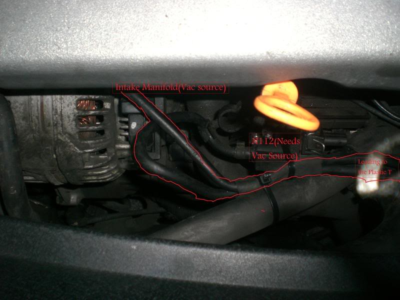
Getting Ready:Remove engine cover(including the one in front of the intake manifold). Also remove the screws from black metal bracket under the intake manifold where i believe the N112 valve is located. It has two hex screws. This enables us to see what we will be working with later.
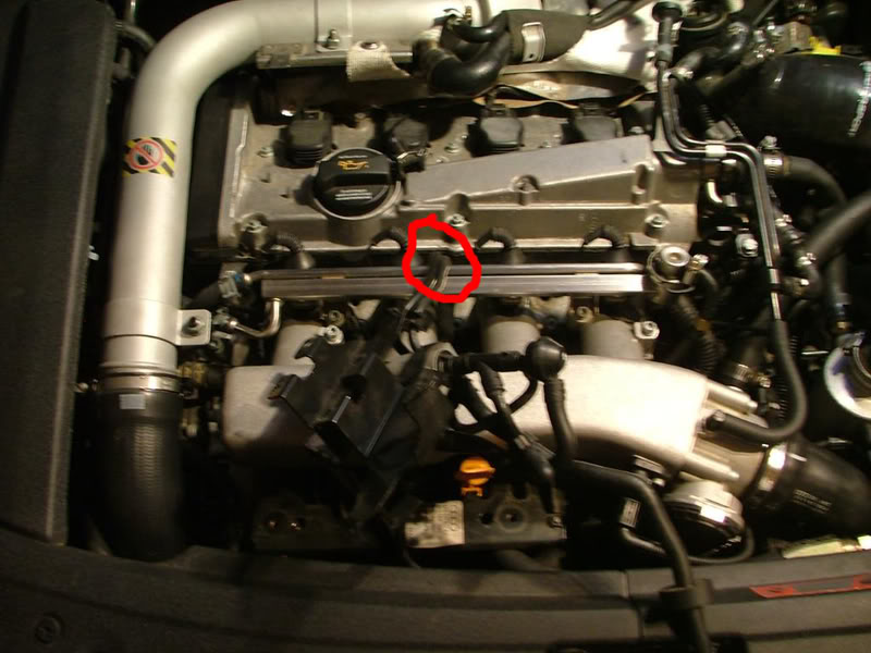
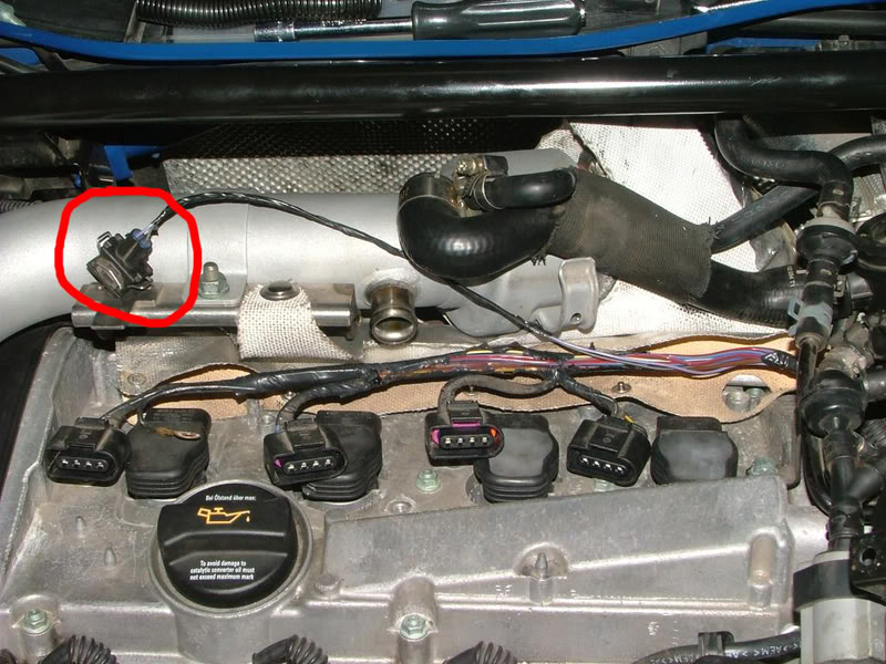
1. Unbolt N249 from top of valve cover, and unplug connector(has purple and grey wire)

2. Cut the two hoses from the n249 going under the intake manifold, cut about an inch away from where it hooks to the n249.
3. Pull the two hoses that are now sitting on top of your valve cover until they are sitting between your radiator fan and your intake manifold. Sorry no pictures of this yet but i will take some tomorrow.
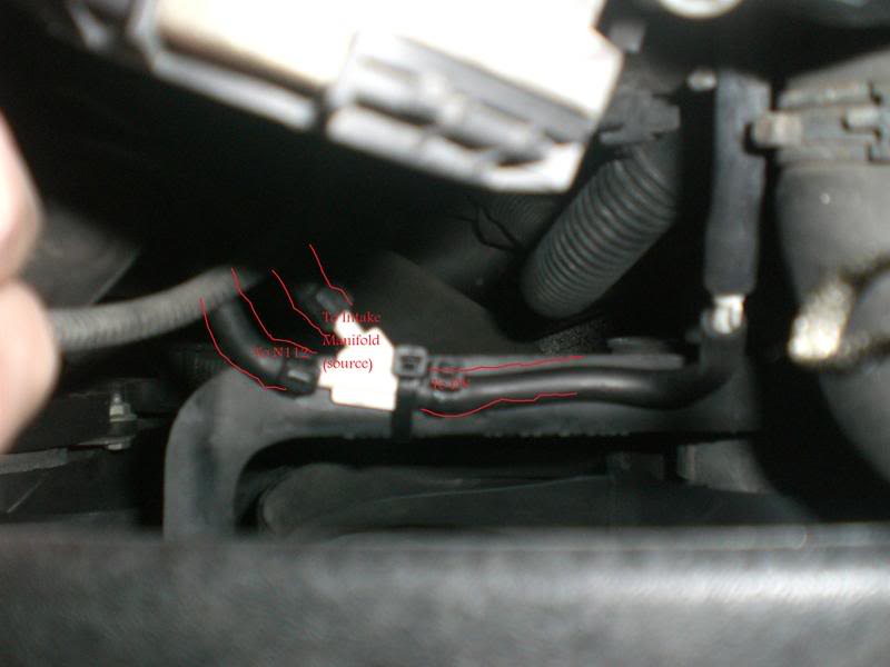
4. Connect the two hoses together with a plastic T that fits snug in the hole of the vac hose(it doesnt matter where you hook them up at on the T). And Zip tie or hose clamp them.
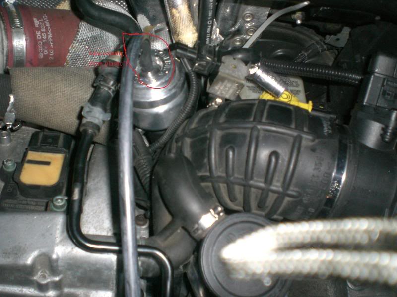
5. With the 2.5 feet of 7/32 vac hose run it from the free spot on the T to the top of your Diverter Valve. Also zip tie or clamp. Pictures tomorrow.
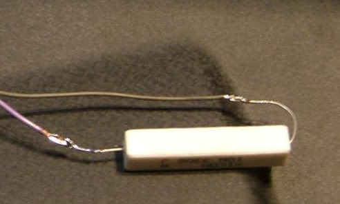
6. Now for the electrical Part, Cut off the connector that use to be plugged into the n249 and take off the black covering to it about 6 inches, just so you can separate the gray and purple wires a good bit.
7. Strip back both the purple and Grey wire about half an inch and solder the resistor between the two, the closer to the main housing of the resistor the better. Make sure you have a good solid connection. Then tape up the whole resistor and wires a few times for protection.
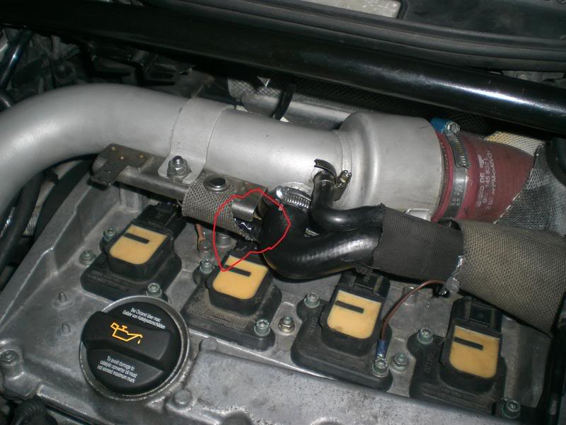
8. Now you can locate the resistor wherever you would like, I put mine in the pocket created by the heat shield and charge pipe.
9. Zip tie everything to make it look pretty.
10. Clean Up your tools and test it out.
Needed: Cost:
Basic Tools(screwdrivers,Hex,sockets,solder and iron,electrical tape,etc) Priceless
2.5 feet 7/32 vac hoses $~1.50
Assortment of plastic T's $~2.00
Wire ties or Small hose clamps $~1.50
330 Ohm 10 Watt resistor $1-5.00
Pictures from l88m22vette delete and mine
Getting Ready:Remove engine cover(including the one in front of the intake manifold). Also remove the screws from black metal bracket under the intake manifold where i believe the N112 valve is located. It has two hex screws. This enables us to see what we will be working with later.
1. Unbolt N249 from top of valve cover, and unplug connector(has purple and grey wire)
2. Cut the two hoses from the n249 going under the intake manifold, cut about an inch away from where it hooks to the n249.
3. Pull the two hoses that are now sitting on top of your valve cover until they are sitting between your radiator fan and your intake manifold. Sorry no pictures of this yet but i will take some tomorrow.
4. Connect the two hoses together with a plastic T that fits snug in the hole of the vac hose(it doesnt matter where you hook them up at on the T). And Zip tie or hose clamp them.
5. With the 2.5 feet of 7/32 vac hose run it from the free spot on the T to the top of your Diverter Valve. Also zip tie or clamp. Pictures tomorrow.
6. Now for the electrical Part, Cut off the connector that use to be plugged into the n249 and take off the black covering to it about 6 inches, just so you can separate the gray and purple wires a good bit.
7. Strip back both the purple and Grey wire about half an inch and solder the resistor between the two, the closer to the main housing of the resistor the better. Make sure you have a good solid connection. Then tape up the whole resistor and wires a few times for protection.
8. Now you can locate the resistor wherever you would like, I put mine in the pocket created by the heat shield and charge pipe.
9. Zip tie everything to make it look pretty.
10. Clean Up your tools and test it out.
Last edited by jhsoccerodp; 01-09-2009 at 09:05 AM. Reason: Update
#2
01-08-2009, 11:47 PM
edited: thats cool, sorry I was shitty, I've had a busy first week of student teaching. I hear you about the cold, I am going to have a garage of spaceheaters for my timing belt (I think its time I get the hell outta the snow belt)...hope the wrenching went well
Last edited by l88m22vette; 01-09-2009 at 12:27 AM.
#3
01-09-2009, 12:07 AM
updated, sorry about that l88m22vette, i will have the actual pictures up from mine in the morning when its not so cold and dark. l88m22vette was the N249 we started with and worked from his and we seemed to make it a bit easier.

#5
01-30-2009, 03:19 PM
the picture under step 4 has it, any plastic T will work as long as it fits inside of the hoses
#6
02-05-2009, 11:26 AM

Here's the big question... Will this work without throwing a code for the SAI. Everytime I mess with the n249 by trying to get rid of it I get a CEL for improper flow on secondary air injection. If this doesn't throw a CEL then you are my hero.
#8
02-05-2009, 06:14 PM

The improper flow cel is only if you remove the sai pump i believe. You can remove the N249 and replace it with a 330ohm 10w resistor and get no code. You can remove the sai and replace the pump with a same resistor to keep from getting a sai pump code but will still throw the improper flow.
#9
02-06-2009, 10:39 PM
right, you wont get an improper flow with just n249 delete, but the sai, you need coolant and a block-off plate, plus get a tuner to remove the code, and apr doesnt do it but i think giac? im not sure does
#10
01-03-2018, 12:51 PM

i am asking cuz i have those coils in the last pic and i noticed many coils ive seen are difrent are they good coils and are they oem ?