FWD Rear Axle Beam Guide Bushing DIY replacement
#1
 10-29-2010, 01:49 AM


First off, this seems to not be covered anywhere for the B5 platform, A4 or Passat. Maybe I wasn't searching the right terms, but Google gave me very little to work with.
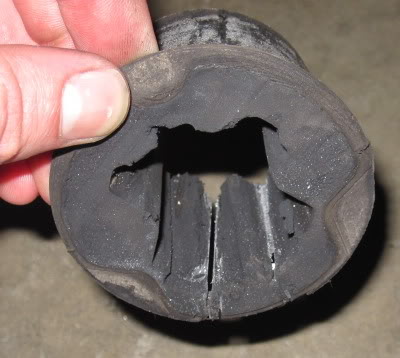
Many FWD A4 B5 models are likely experiencing worn bushings if the bushings are still factory original. I have looked into this because of a crash that led me to purchase a used rear axle beam of a '99 A4 FWD, at which point it seemed best to replace the bushings. After finagling with the old bushings, I could tell that they were pretty worn and there were obvious signs of cracking on the rubber. And who knows how long that car sat in the junk yard...
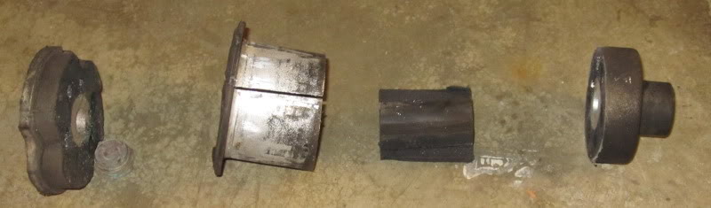
So, when the axle beam is removed from the car (this is detailed in most service manuals), you will find the bushings extremely difficult to remove. Pretty much impossible IMO. I ended up cutting mine into 4 different pieces, using just a sawz-all and small (6 1/2") coping saw.
Here's how the bushing sits in the axle beam:
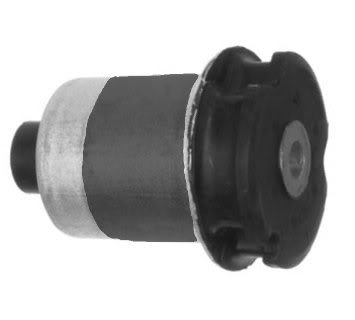
Where the gray part is the part you cannot see because it is enclosed by the axle beam.
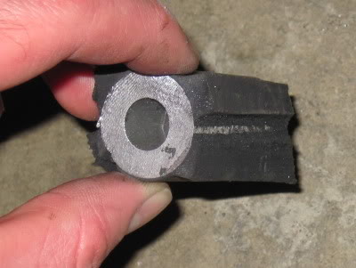
First will be cutting the ends off with a sawz-all, specifically the blue shaded parts:
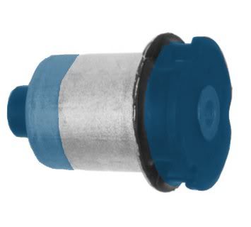
This makes it so that the aluminum inner core will now only be attached to the bushing itself by the internal rubber webbing.
Speaking of the rubber webbing, you now take your coping saw blade off the saw and stick it through the webbing. Hopefully you're using a wood blade with something along the lines of 10 teeth per inch to make your life easier.
Cut through all the webbing (should be 4 cuts basically), and push out the center piece.
There will be left the outer aluminum portion of the bushing. This will need to be slotted with the sawz-all like this (on the inside of the bushing, of course):
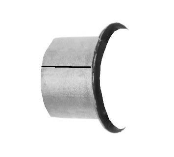
Try to cut all the way through the aluminum outer wall without cutting into the axle beam itself. This is easier said than done... I slightly cut into the axle beam on both sides, but it shouldn't be nearly enough to weaken anything.
Now the outer part of the bushing can be easily pried out with a screw driver! That's pretty much it. I haven't installed my new bushings yet and I will update this thread when I do (possibly with a DIY procedure/pics), but I can tell it will be a HUGE PITA.
Some VW forums I've read up on say to use dry ice to shrink the bushing, and heat up the axle beam to expand it. I will be doing both to maximize ease-of-fitting, along with a length of 3/8"-16 all thread and some nuts to pull the bushings into the axle beam.
BTW, here is the cheapest guide bushing you will find:
http://www.autohausaz.com/search/pro...FQoTbAod6APOEA
2 are required, 1 per side. These are made by Meyle so I would expect the quality to be half-way decent.
Hope this helps somebody with a FWD (which this place needs more love for LOL) with a creaking rear end!
Many FWD A4 B5 models are likely experiencing worn bushings if the bushings are still factory original. I have looked into this because of a crash that led me to purchase a used rear axle beam of a '99 A4 FWD, at which point it seemed best to replace the bushings. After finagling with the old bushings, I could tell that they were pretty worn and there were obvious signs of cracking on the rubber. And who knows how long that car sat in the junk yard...
So, when the axle beam is removed from the car (this is detailed in most service manuals), you will find the bushings extremely difficult to remove. Pretty much impossible IMO. I ended up cutting mine into 4 different pieces, using just a sawz-all and small (6 1/2") coping saw.
Here's how the bushing sits in the axle beam:
Where the gray part is the part you cannot see because it is enclosed by the axle beam.
First will be cutting the ends off with a sawz-all, specifically the blue shaded parts:
This makes it so that the aluminum inner core will now only be attached to the bushing itself by the internal rubber webbing.
Speaking of the rubber webbing, you now take your coping saw blade off the saw and stick it through the webbing. Hopefully you're using a wood blade with something along the lines of 10 teeth per inch to make your life easier.
Cut through all the webbing (should be 4 cuts basically), and push out the center piece.
There will be left the outer aluminum portion of the bushing. This will need to be slotted with the sawz-all like this (on the inside of the bushing, of course):
Try to cut all the way through the aluminum outer wall without cutting into the axle beam itself. This is easier said than done... I slightly cut into the axle beam on both sides, but it shouldn't be nearly enough to weaken anything.
Now the outer part of the bushing can be easily pried out with a screw driver! That's pretty much it. I haven't installed my new bushings yet and I will update this thread when I do (possibly with a DIY procedure/pics), but I can tell it will be a HUGE PITA.
Some VW forums I've read up on say to use dry ice to shrink the bushing, and heat up the axle beam to expand it. I will be doing both to maximize ease-of-fitting, along with a length of 3/8"-16 all thread and some nuts to pull the bushings into the axle beam.
BTW, here is the cheapest guide bushing you will find:
http://www.autohausaz.com/search/pro...FQoTbAod6APOEA
2 are required, 1 per side. These are made by Meyle so I would expect the quality to be half-way decent.
Hope this helps somebody with a FWD (which this place needs more love for LOL) with a creaking rear end!
Last edited by MetalMan; 11-07-2010 at 06:56 PM.
#2
11-07-2010, 07:22 PM
Now for installing the bushings, this is by NO means a straightforward process. Took more than I thought it would. Guess that's why Audi/VW have a very specialized tool for this procedure.
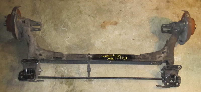
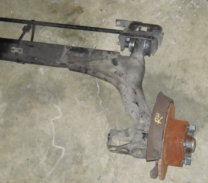
Just for reference, this is the completed axle beam (with new guide bushings installed) except for a couple brackets that hold the brake lines and e-brake cables, and the rest of the brakes. I will be reusing my brake rotors...
The junkyard marked RH and LH which is left-hand and right-hand, obviously. It's a good reference.
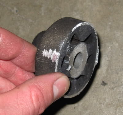
Here are closeups on an installed bushing:
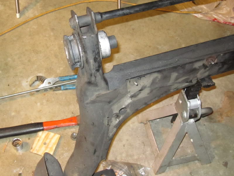
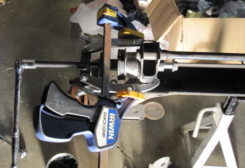
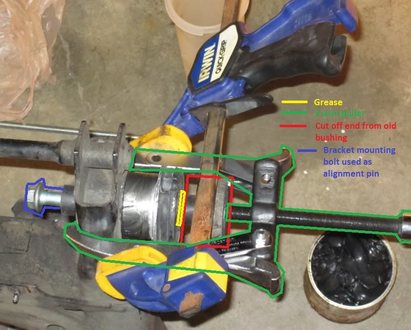
This is the bushing installed hand-tight, with my installation fixture:
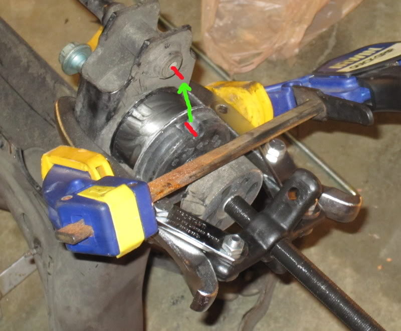
Keep in mind that the bushing does need to be installed with the proper orientation; the deeper notch needs to be closest to the reinforcement bar, and it can kinda be seen in the pictures.
Essentially it's a 2-arm puller (it's actually a 2 or 3 arm puller) converted for pushing duties. Part of the cut up old bushing is used as an interface between the puller screw end and the new bushing, with some grease between the cut off piece and new bushing (since the cut off piece will be spinning with the screw on the puller directly against the new bushing). There is also the blue/yellow clamp there to ensure that the arms of the puller won't fling off and hit me in the face. This should help clarify:
Also, the bushings won't slide in without help. The first bushing I did took forever. Turns out freezing the bushing with dry ice and heating the axle beam with a torch doesn't help. I applied bearing grease on the bushing, and inside the axle beam where the bushing goes. On the other side, I also slightly reduced the diameter of the bushing by chucking it into my drill press and taking a file/sand paper to it. This one is still an extremely tight fit, and it went in MUCH easier than the first one did.
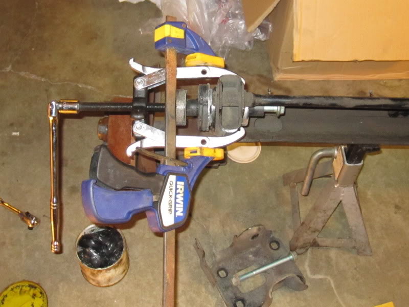
The bushing part-way in:
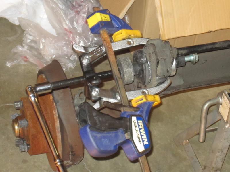
And the bushing pushed in completely:

So, all-in-all this can be a DIY job... But it's a pain in the *** no matter what. If I were to go back and do this ENTIRE job over again starting with the same equipment (axle beam already out of car), it would probably take me 5 hours.
Just for reference, this is the completed axle beam (with new guide bushings installed) except for a couple brackets that hold the brake lines and e-brake cables, and the rest of the brakes. I will be reusing my brake rotors...
The junkyard marked RH and LH which is left-hand and right-hand, obviously. It's a good reference.
Here are closeups on an installed bushing:
This is the bushing installed hand-tight, with my installation fixture:
Keep in mind that the bushing does need to be installed with the proper orientation; the deeper notch needs to be closest to the reinforcement bar, and it can kinda be seen in the pictures.
Essentially it's a 2-arm puller (it's actually a 2 or 3 arm puller) converted for pushing duties. Part of the cut up old bushing is used as an interface between the puller screw end and the new bushing, with some grease between the cut off piece and new bushing (since the cut off piece will be spinning with the screw on the puller directly against the new bushing). There is also the blue/yellow clamp there to ensure that the arms of the puller won't fling off and hit me in the face. This should help clarify:
Also, the bushings won't slide in without help. The first bushing I did took forever. Turns out freezing the bushing with dry ice and heating the axle beam with a torch doesn't help. I applied bearing grease on the bushing, and inside the axle beam where the bushing goes. On the other side, I also slightly reduced the diameter of the bushing by chucking it into my drill press and taking a file/sand paper to it. This one is still an extremely tight fit, and it went in MUCH easier than the first one did.
The bushing part-way in:
And the bushing pushed in completely:
So, all-in-all this can be a DIY job... But it's a pain in the *** no matter what. If I were to go back and do this ENTIRE job over again starting with the same equipment (axle beam already out of car), it would probably take me 5 hours.
Last edited by MetalMan; 11-25-2010 at 08:26 PM.
#4
11-07-2010, 08:52 PM
Very nicely done. I'll leave this here for a couple days for publicity and then move it to the DIY section. Any additional info you care to add can be added at any time.
#6
11-07-2010, 09:25 PM
Thanks guys! The pictures weren't the best due to crappy lighting at night, so I hope it still gets the point across.
On Thursday (Veteran's Day, no school!) I'll actually be doing the axle beam swap. It is my goal to get pictures of removal/installation and complete this DIY. FWD needs more love LOL.
On Thursday (Veteran's Day, no school!) I'll actually be doing the axle beam swap. It is my goal to get pictures of removal/installation and complete this DIY. FWD needs more love LOL.
#7
11-08-2010, 07:19 AM
Sounds good. Once you're satisfied with the procedure, just let me know and I'll put it into the DIY area for everyone's use.
#8
11-25-2010, 07:42 PM
The axle beam has been swapped. Unfortunately due to time constraints I didn't get any pictures... and I know pictures are worth a thousand words. But to use the camera (my mom's) I would have needed clean hands and there's no way I could have washed my hands that many times and finished the swap in the time I had. Though in my opinion anybody who is attempting to remove the axle beam shouldn't necessarily need pictures of removing the axle beam.
That said.... It's a very straight-forward procedure. I didn't take notes so whatever I write here is straight from memory (should be pretty accurate, though it's been a couple weeks):
-sockets: 8mm, 13mm, 15mm, 16mm, 18mm, and 17mm for wheel bolts
-wrenches: 11mm, 13mm, 15mm, 16mm, 18mm
-allens: 6mm, and it was either 7mm or 8mm to get the bolts that hold the caliper brackets to the axle (this allen needs to be strong, those bolts get torqued in TIGHT!)
-an extra helper is VERY handy, especially when it comes to putting the axle beam back in. I suppose you could replace a person with a floor jack, but you can save A LOT of time with another person working on one side while you work on the other.
-floor jack - it was nice to have TWO floor jacks handy, one for each side to make sure both sides went up evenly
-jack stands - TWO jack stands were all that I needed, but if only one floor jack is available to you then an additional jack stand or two would be beneficial
-container to catch brake fluid
-DOT4 brake fluid
For starters, the back end needs to be jacked up and put on jack stands, and the back wheels removed. Make sure the e-brake is disengaged. Then all the back brake calipers and caliper brackets need to be removed. You can leave the brake calipers hanging from a piece of string attached to the springs to keep them from hanging by the brake hoses. The center cap on the brake rotor needs to be popped off (I usually use a chisel and work it off), and the cotter pin needs to be removed. Cotter pins should NEVER be reused, so clean the one you just removed and take it to a hardware store to find a replacement. Now the rotor will slide off, but keep in mind the outer bearing and thrust washer will fall off first, so be ready to catch them.
ALTERNATIVELY: this would be a good time to replace the back rotors, bearings, and brake pads if yours are worn. Bearing kits come with new bearings/races, seals, cotter pins, and outer grease caps. The bearing races don't necessarily need to be pressed on - I just simply used a flat-head screwdriver and hammer to pound them into the new rotors. Just be careful that the screwdriver doesn't slip and mar the surface of the races, as that would ruin the point of replacing them. Greasing the bearings is a requirement, so a good bearing grease is in order. Also grease the inner dust shield.
On each side of the top of the axle beam is a bracket that holds the e-brake cable, ABS sensor cable, and brake lines/hoses in place. This bracket doesn't need to be removed from the car, but it needs to be removed from the axle beam. There are 3 nuts holding each on, and they are removed with an 8mm socket and just a tiny bit of torque.
With the brackets loose, you can remove the ABS sensors from their positions in the axle beam, and leave them hanging in a place that's out of the way. Next brake hoses will need to be disconnected... There are 2 separate brake hoses that attach to a solid brake line. Only one of them (per side) actually needs to be removed if ONLY the axle beam is removed, as one brake hose attaches to the bracket mentioned above (the hose that NEEDS to be removed), and the other attaches to the axle beam mounting bracket. The brake hoses are undone with a 13mm (I believe) wrench. Make sure the fluid drains into your container, but ASSUME that brake fluid will get everywhere, because it will.
At this point you have a choice: if you are replacing the entire axle beam like I did it will be easiest to remove the stub axles and brake shields now to gain more clearance. There are 5-6 allen bolts holding each stub axle in, and the allen size is one of the sizes I listed.
Now the bolts holding the shocks to the axle beam can be removed. I don't remember which size socket and wrench to use, but it's one of the sizes listed previously. There's the bolt head closer to the middle of the car, and a nut that can be accessed with a wrench through the opening in the side of the axle beam (this is easier with the brake shield removed). Watch out for spacers that might sit next to the shock absorber lower bushing on some aftermarket shocks - I have Bilsteins and my one my spacers went missing so I had to make a trip to the hardware store to get something as a replacement.
Lastly, the only things holding the axle beam in are the bolts that hold the guide bushings to the axle beam mounting brackets. The nuts can be removed (18mm socket and wrench I wanna say). Here it helps to have somebody around, because once those bolts come out the axle beam will drop. And that's it!
However, if you also want to replace the axle beam mounting brackets like I did, you certainly can. Keep in mind though that these brackets control the alignment of the back end - the tracking (side-to-side positioning), and the relative toe (toe can't be adjusted per-se, but it can be centered). So if you remove these brackets, you will have to center the toe and make sure the side-to-side positioning of the axle beam is centered when you put the brackets back on. Before removing these brackets, though, there is another brake hose on each side that needs to be removed.
Installation is the reverse of removal. Here are the torque specs pulled from an Audi service manual:
-Bolt/nut holding guide bushing to axle beam mounting bracket: 59 ft-lb **
-Bolt/nut holding shock bottom to axle beam: 37 ft-lb **
-Bolts holding axle beam mounting brackets to chassis (if you removed them): 55 ft-lb *
-Bolts holding stub axle and brake shields to axle beam: 22 ft-lb
-Brake caliper bracket bolts to axle beam: 70 ft-lb
-Slider pin bolts (hold brake calipers to brake caliper brackets): 26 ft-lb
* means these are tightened after everything else is completed, and axle beam has been centered (toe and tracking)
** indicates these are tightened when suspension is compressed to normal ride height. I like to use jack stands resting under the axle beam, one on each side, to get the suspension compressed. Tightening these when the suspension is compressed will properly pre-load the bushings so they don't wear prematurely.
Insert guide bushing bolts while holding the axle beam up. Hand-tighten nuts. Lift axle beam and line up lower shock bushings on each side, a helper is handy here. If your shocks use a spacer, place the spacer in. Insert the lower shock mounting bolts, and hand-tighten the nuts. Reinstall the brake hose/ABS/e-brake bracket to the top of the axle beam, making sure all cabled and wires are properly tucked under it. Put the 3 nuts back on with just enough torque to snug them down. Insert the ABS sensors, but don't push them in all the way yet.
If you installed new brake rotors and brake pads, you will need a rotating brake piston retractor tool to push the brake piston back in (watch the brake fluid reservoir level and make sure it doesn't spill fluid out). Reattach the brake hoses, and tighten with as much torque as you removed them with. Reinstall brake rotors, outer bearing, thrust washer, nut (tighten this as tight as you can while the rotor still spins freely), castle nut, cotter pin (bend both legs), and grease cap. Make sure you had the bearings well greased. Now spin the brake rotor, and slowly push the ABS sensor in until you hear it start to rub the ABS ring on the rotor, and back it out just a bit. If the sensor is too close to the ABS ring, it will be damaged. If the sensor is too far from the ring, your ABS won't work properly (guess how I figured that one out).
Reinstall the brake caliper brackets. Insert brake pads into brake caliper brackets, but make sure they won't fall out. Install brake calipers, tightening these bolts requires that you use a wrench to keep the slider pin from rotating.
Now would be a good time to bleed the brakes (don't need engine assist for this). Do the passenger side first. Start by putting a (clear) hose on the nipple and put the other end of the hose into your [old] brake fluid container. Loosen the nipple with an 11mm wrench. Have someone pump the brake pedal but not push it too far, while you watch the brake fluid flow through the hose. When it's pure fluid/no air in the hose, tighten the nipple. Now do the driver side, following the same procedure. While doing this, you'll want to make sure the brake fluid reservoir level does not dip too low. You can fill it as old fluid is pumped out while bleeding.
This is the point where I put the wheels back on with the bolts slightly tight (can't tighten them with the tires off the ground...). With 2 jacks I jacked up the back end via the axle beam, and placed the jacks under that axle beam so the car could rest its weight on the springs and compress them. The guide bushing bolts and lower shock mounting bolts can now be tightened to their specific torques.
If you removed the axle beam mounting brackets, this is the time to align the axle beam. For me this was BY FAR the most difficult part of this entire job. I ended up using the car's body as a reference, to get the toe on each side equalized, and the side-to-side tracking centered. I used a metal ruler lined up with the wheel to get the toe centered, and checked the gap between the wheel and fender on each side to make sure they matched. It helps to slightly tighten one or two of the axle beam mounting bracket bolts to keep the axle beam from sliding around while aligning it, and when it's aligned you can tighten down all of them to their specified torque.
Now go for a drive It may be worthwhile to get a professional to align the rear axle beam to ensure toe and tracking are right, to prevent excessive tire wear.
That said.... It's a very straight-forward procedure. I didn't take notes so whatever I write here is straight from memory (should be pretty accurate, though it's been a couple weeks):
-sockets: 8mm, 13mm, 15mm, 16mm, 18mm, and 17mm for wheel bolts
-wrenches: 11mm, 13mm, 15mm, 16mm, 18mm
-allens: 6mm, and it was either 7mm or 8mm to get the bolts that hold the caliper brackets to the axle (this allen needs to be strong, those bolts get torqued in TIGHT!)
-an extra helper is VERY handy, especially when it comes to putting the axle beam back in. I suppose you could replace a person with a floor jack, but you can save A LOT of time with another person working on one side while you work on the other.
-floor jack - it was nice to have TWO floor jacks handy, one for each side to make sure both sides went up evenly
-jack stands - TWO jack stands were all that I needed, but if only one floor jack is available to you then an additional jack stand or two would be beneficial
-container to catch brake fluid
-DOT4 brake fluid
For starters, the back end needs to be jacked up and put on jack stands, and the back wheels removed. Make sure the e-brake is disengaged. Then all the back brake calipers and caliper brackets need to be removed. You can leave the brake calipers hanging from a piece of string attached to the springs to keep them from hanging by the brake hoses. The center cap on the brake rotor needs to be popped off (I usually use a chisel and work it off), and the cotter pin needs to be removed. Cotter pins should NEVER be reused, so clean the one you just removed and take it to a hardware store to find a replacement. Now the rotor will slide off, but keep in mind the outer bearing and thrust washer will fall off first, so be ready to catch them.
ALTERNATIVELY: this would be a good time to replace the back rotors, bearings, and brake pads if yours are worn. Bearing kits come with new bearings/races, seals, cotter pins, and outer grease caps. The bearing races don't necessarily need to be pressed on - I just simply used a flat-head screwdriver and hammer to pound them into the new rotors. Just be careful that the screwdriver doesn't slip and mar the surface of the races, as that would ruin the point of replacing them. Greasing the bearings is a requirement, so a good bearing grease is in order. Also grease the inner dust shield.
On each side of the top of the axle beam is a bracket that holds the e-brake cable, ABS sensor cable, and brake lines/hoses in place. This bracket doesn't need to be removed from the car, but it needs to be removed from the axle beam. There are 3 nuts holding each on, and they are removed with an 8mm socket and just a tiny bit of torque.
With the brackets loose, you can remove the ABS sensors from their positions in the axle beam, and leave them hanging in a place that's out of the way. Next brake hoses will need to be disconnected... There are 2 separate brake hoses that attach to a solid brake line. Only one of them (per side) actually needs to be removed if ONLY the axle beam is removed, as one brake hose attaches to the bracket mentioned above (the hose that NEEDS to be removed), and the other attaches to the axle beam mounting bracket. The brake hoses are undone with a 13mm (I believe) wrench. Make sure the fluid drains into your container, but ASSUME that brake fluid will get everywhere, because it will.
At this point you have a choice: if you are replacing the entire axle beam like I did it will be easiest to remove the stub axles and brake shields now to gain more clearance. There are 5-6 allen bolts holding each stub axle in, and the allen size is one of the sizes I listed.
Now the bolts holding the shocks to the axle beam can be removed. I don't remember which size socket and wrench to use, but it's one of the sizes listed previously. There's the bolt head closer to the middle of the car, and a nut that can be accessed with a wrench through the opening in the side of the axle beam (this is easier with the brake shield removed). Watch out for spacers that might sit next to the shock absorber lower bushing on some aftermarket shocks - I have Bilsteins and my one my spacers went missing so I had to make a trip to the hardware store to get something as a replacement.
Lastly, the only things holding the axle beam in are the bolts that hold the guide bushings to the axle beam mounting brackets. The nuts can be removed (18mm socket and wrench I wanna say). Here it helps to have somebody around, because once those bolts come out the axle beam will drop. And that's it!
However, if you also want to replace the axle beam mounting brackets like I did, you certainly can. Keep in mind though that these brackets control the alignment of the back end - the tracking (side-to-side positioning), and the relative toe (toe can't be adjusted per-se, but it can be centered). So if you remove these brackets, you will have to center the toe and make sure the side-to-side positioning of the axle beam is centered when you put the brackets back on. Before removing these brackets, though, there is another brake hose on each side that needs to be removed.
Installation is the reverse of removal. Here are the torque specs pulled from an Audi service manual:
-Bolt/nut holding guide bushing to axle beam mounting bracket: 59 ft-lb **
-Bolt/nut holding shock bottom to axle beam: 37 ft-lb **
-Bolts holding axle beam mounting brackets to chassis (if you removed them): 55 ft-lb *
-Bolts holding stub axle and brake shields to axle beam: 22 ft-lb
-Brake caliper bracket bolts to axle beam: 70 ft-lb
-Slider pin bolts (hold brake calipers to brake caliper brackets): 26 ft-lb
* means these are tightened after everything else is completed, and axle beam has been centered (toe and tracking)
** indicates these are tightened when suspension is compressed to normal ride height. I like to use jack stands resting under the axle beam, one on each side, to get the suspension compressed. Tightening these when the suspension is compressed will properly pre-load the bushings so they don't wear prematurely.
Insert guide bushing bolts while holding the axle beam up. Hand-tighten nuts. Lift axle beam and line up lower shock bushings on each side, a helper is handy here. If your shocks use a spacer, place the spacer in. Insert the lower shock mounting bolts, and hand-tighten the nuts. Reinstall the brake hose/ABS/e-brake bracket to the top of the axle beam, making sure all cabled and wires are properly tucked under it. Put the 3 nuts back on with just enough torque to snug them down. Insert the ABS sensors, but don't push them in all the way yet.
If you installed new brake rotors and brake pads, you will need a rotating brake piston retractor tool to push the brake piston back in (watch the brake fluid reservoir level and make sure it doesn't spill fluid out). Reattach the brake hoses, and tighten with as much torque as you removed them with. Reinstall brake rotors, outer bearing, thrust washer, nut (tighten this as tight as you can while the rotor still spins freely), castle nut, cotter pin (bend both legs), and grease cap. Make sure you had the bearings well greased. Now spin the brake rotor, and slowly push the ABS sensor in until you hear it start to rub the ABS ring on the rotor, and back it out just a bit. If the sensor is too close to the ABS ring, it will be damaged. If the sensor is too far from the ring, your ABS won't work properly (guess how I figured that one out).
Reinstall the brake caliper brackets. Insert brake pads into brake caliper brackets, but make sure they won't fall out. Install brake calipers, tightening these bolts requires that you use a wrench to keep the slider pin from rotating.
Now would be a good time to bleed the brakes (don't need engine assist for this). Do the passenger side first. Start by putting a (clear) hose on the nipple and put the other end of the hose into your [old] brake fluid container. Loosen the nipple with an 11mm wrench. Have someone pump the brake pedal but not push it too far, while you watch the brake fluid flow through the hose. When it's pure fluid/no air in the hose, tighten the nipple. Now do the driver side, following the same procedure. While doing this, you'll want to make sure the brake fluid reservoir level does not dip too low. You can fill it as old fluid is pumped out while bleeding.
This is the point where I put the wheels back on with the bolts slightly tight (can't tighten them with the tires off the ground...). With 2 jacks I jacked up the back end via the axle beam, and placed the jacks under that axle beam so the car could rest its weight on the springs and compress them. The guide bushing bolts and lower shock mounting bolts can now be tightened to their specific torques.
If you removed the axle beam mounting brackets, this is the time to align the axle beam. For me this was BY FAR the most difficult part of this entire job. I ended up using the car's body as a reference, to get the toe on each side equalized, and the side-to-side tracking centered. I used a metal ruler lined up with the wheel to get the toe centered, and checked the gap between the wheel and fender on each side to make sure they matched. It helps to slightly tighten one or two of the axle beam mounting bracket bolts to keep the axle beam from sliding around while aligning it, and when it's aligned you can tighten down all of them to their specified torque.
Now go for a drive
It may be worthwhile to get a professional to align the rear axle beam to ensure toe and tracking are right, to prevent excessive tire wear.
#9
06-15-2012, 11:10 AM

Am I glad I found this....my rear end seems sloppy (no pun intened). Could this be the bushings? I've been to several alignment shops and all tell me the rear beams can not be aligned even the bentley doesn't mention anything about it. I have a major difference from one side to the other, its like a 5 to 8mm difference.
How does the rear feel now? is it stiffer?
How does the rear feel now? is it stiffer?
#10
06-15-2012, 11:26 AM
Am I glad I found this....my rear end seems sloppy (no pun intened). Could this be the bushings? I've been to several alignment shops and all tell me the rear beams can not be aligned even the bentley doesn't mention anything about it. I have a major difference from one side to the other, its like a 5 to 8mm difference.
How does the rear feel now? is it stiffer?
How does the rear feel now? is it stiffer?
Do you have the Factory Service Manual? It actually mentions aligning the axle beam, and how to do it. In fact I have a copy of it printed out and sitting on my desk right now, because I need a full front/rear alignment

I imagine your air ride setup could wreak havoc on those bushings. These bushings are similar to the front lower control arm bushings in the sense that the bolt going through them should be tightened only with the vehicle supporting its own weight.