
My very own update thread


Thread Starter
|
Site Moderator/B5 Tech Guru
Joined: Feb 2010
Posts: 1,745
From: Bay Area, CA
******' lovely. Spent ~10 hours today pulling the axle flange and transmission side cover to replace the magnetic ring inside and I'm still getting VSS implausible signal. Speedometer works intermittently.
I don't know where else to start looking and I'm beyond frustrated. Way too much time and $ to try and get a working speedometer and no CEL...
I don't know where else to start looking and I'm beyond frustrated. Way too much time and $ to try and get a working speedometer and no CEL...

1st Gear
Joined: Sep 2013
Posts: 113
From: Santa Cruz
Does the ECM get it from the cluster? If so u may want to check your wires or cluster. Just thinking. I can look at the schematic at work on Monday
Last edited by smittylube; Oct 8, 2013 at 12:13 PM. Reason: add sig
Thread Starter
|
Site Moderator/B5 Tech Guru
Joined: Feb 2010
Posts: 1,745
From: Bay Area, CA
Thanks smitty.
Here is my trace of the circuit:
From the VSS the signal passes through a brown/red wire into the instrument cluster through pin 23 on the blue connector. After going through the cluster processor/speedometer it passes out through a white/blue wire on pin 6 of the yellow cluster plug into pin 20 of the ECU. Because my car was made before 8/97, the same signal from pin 6 on the yellow cluster plug goes to the cruise control module, pin 9.
Since my cluster doesn't seem to be receiving the signal I'm going to start with the wiring from the VSS to the cluster and see if there are any problems. Then I'll dig into the CC module.
Unfortunately I won't have access to the garage for a few more days.
Last edited by BaseDrifter; Oct 7, 2013 at 12:48 PM.
2nd Gear
Joined: Jul 2011
Posts: 843
From: Kirkland, WA
Do you have access to an oscilloscope? If so, you could probe the plug at the base of the sensor and then again at the cluster to see if the pulses are going through. From the pictures I've seen, it appears that the VSS is based on the speed of the driver's front wheel. If you just jack up the front and spin that wheel, you should get a signal if all is well.
Thread Starter
|
Site Moderator/B5 Tech Guru
Joined: Feb 2010
Posts: 1,745
From: Bay Area, CA
Nope, no oscilloscope. I'm going to start by running an extension off the brown/red wire back to the cluster to check for continuity and see if I have a broken wire. Then jack the car up, spin the wheel, and see if I get a voltage change.
1st Gear
Joined: Sep 2013
Posts: 113
From: Santa Cruz
Your in the city right? I'm in Mt view. not far. I do have a lab scope. You should check for voltage and ground to the sensor if you have a fluke meter or similar.
If you want you can come by the shop and we can sort it out.
If you want you can come by the shop and we can sort it out.
Thread Starter
|
Site Moderator/B5 Tech Guru
Joined: Feb 2010
Posts: 1,745
From: Bay Area, CA
Thanks for the offer Smitty, I'll let you know if I can't get it sorted. I'm over in Berkeley right now.
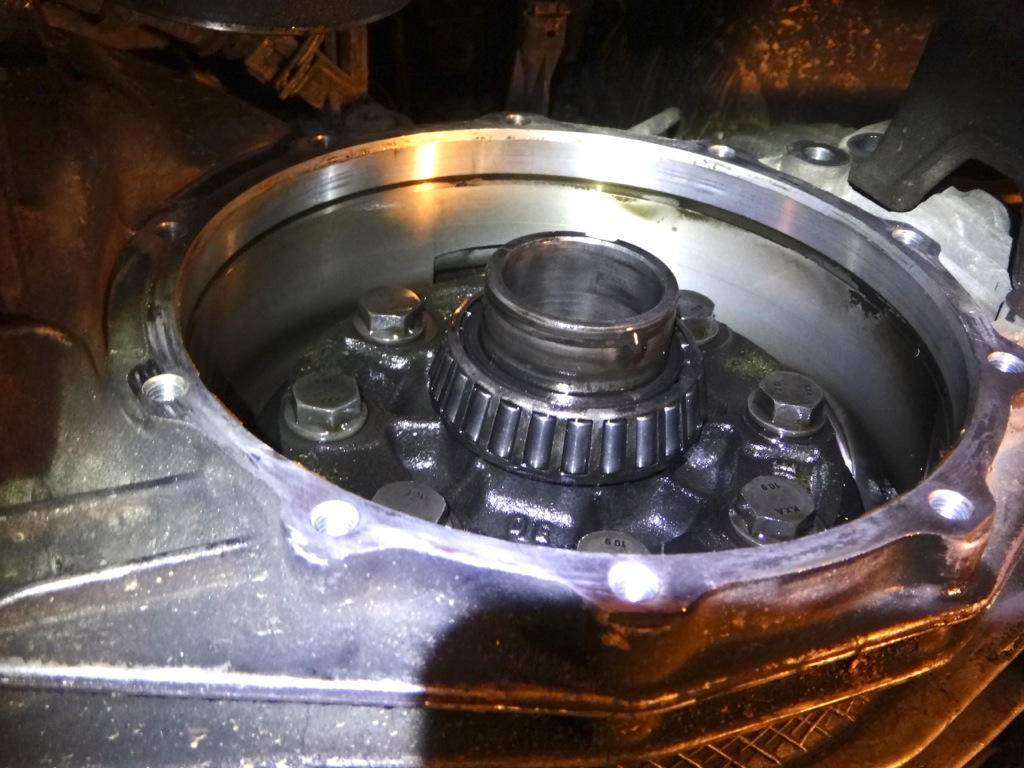
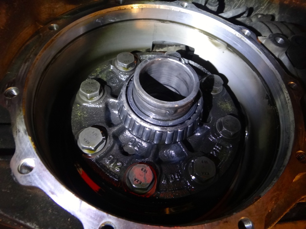
Here are the rest of the pictures from changing the VSS gear ring. I was in a rush so didn't take as many pictures as normal.
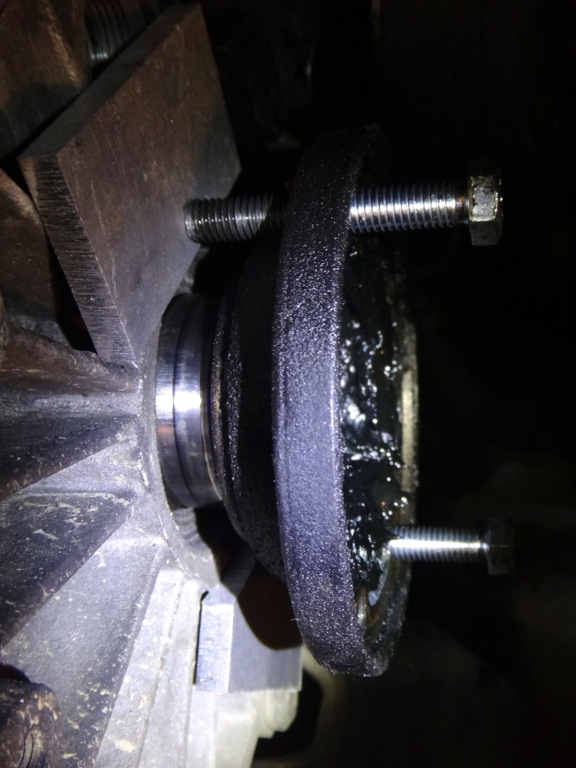
Two M8x1.25 bolts being used to drive out the output flange. Using a couple pieces of aluminum to protect the transmission cover.
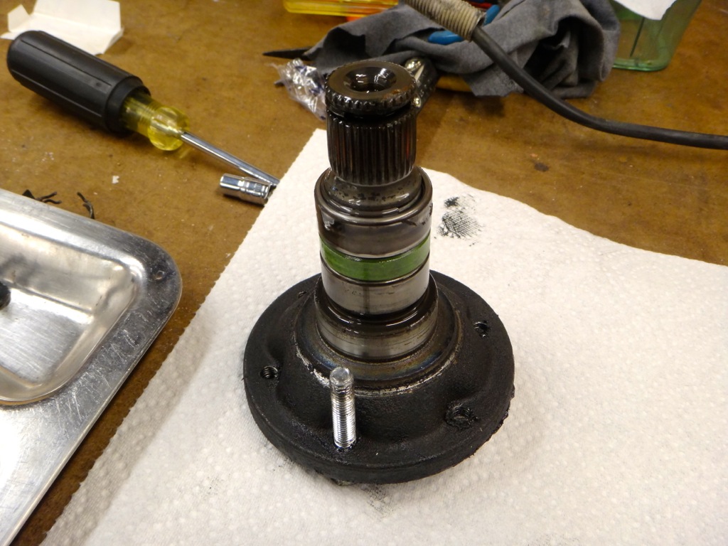
Output flange removed.
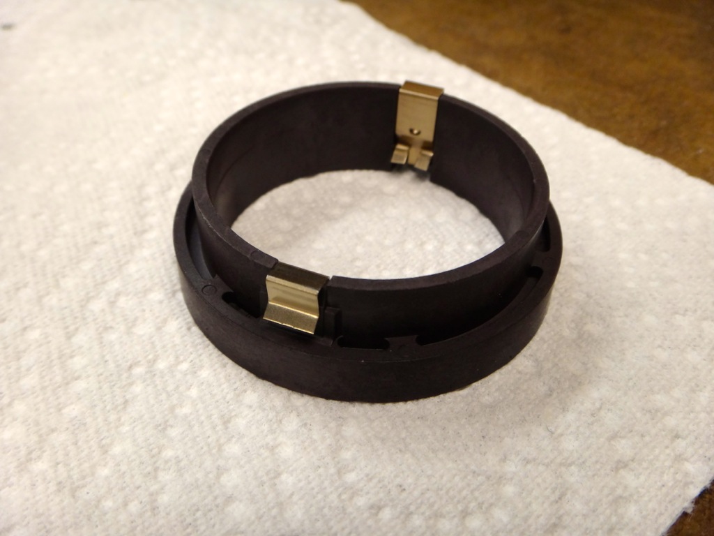
New gear ring.
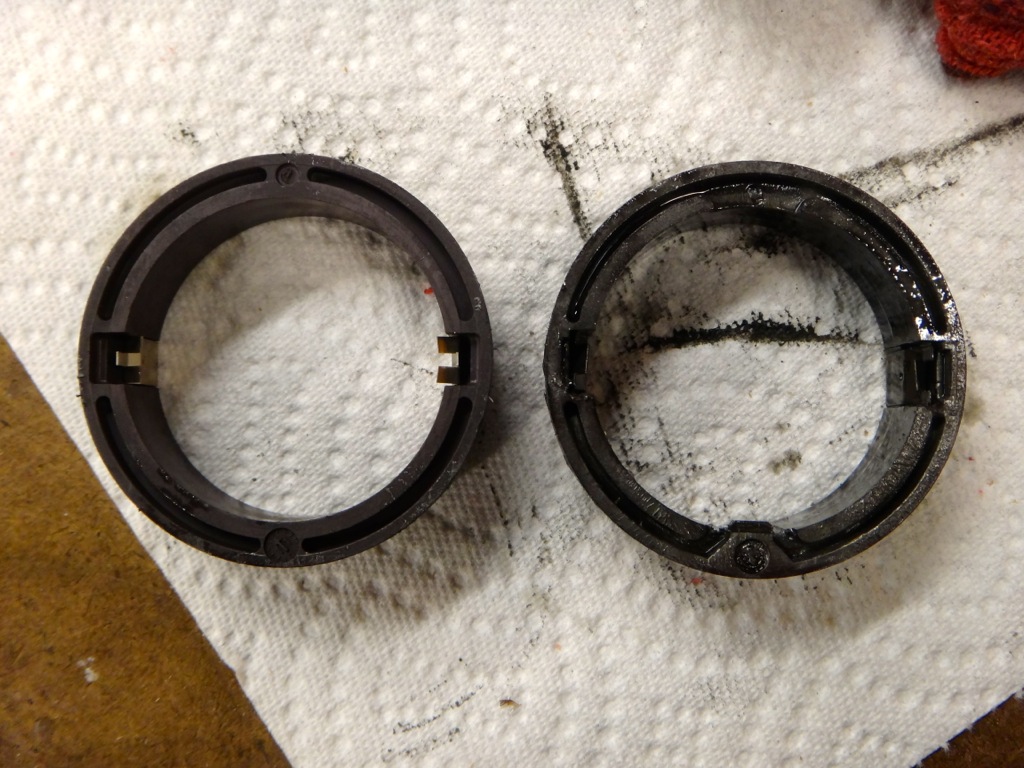
Old compared to the new. Notice the lack of a "locating tab" on the new ring. It ended up locking into place with the side clips anyways.
Transmission side cover removed, gear ring uninstalled.
Here are the rest of the pictures from changing the VSS gear ring. I was in a rush so didn't take as many pictures as normal.
Two M8x1.25 bolts being used to drive out the output flange. Using a couple pieces of aluminum to protect the transmission cover.

Output flange removed.

New gear ring.

Old compared to the new. Notice the lack of a "locating tab" on the new ring. It ended up locking into place with the side clips anyways.

Transmission side cover removed, gear ring uninstalled.

