DIY: B5 Control Arms and Tie Rod End Assemblies, Part 1: Preparation
#1
 08-25-2011, 10:44 AM

Alright, alright. It's time to save some money and have some fun by changing these components ourselves.
This job was by far the most challenging one I've attempted on my B5, yet it went the smoothest of all the jobs I've done. While researching and preparing to do this job, all of the DIY's I found seemed to be tailored to the seasoned amateur mechanic, so I decided to do a DIY for those of us who have far less experience. All of the suggestions and advice I give here were given to me by others on this forum who are far more experienced than I am. In fact, I don't think I had an original thought in this whole series. All I did was take pictures and organize the great advice I got from others into this DIY.
I'm using so many pictures that I have to split this into multiple threads. I have therefore decided to split this into four parts:
1) Preparation
2) Replacing the Inner and Outer Tie Rod Assemblies
3) Replacing the Upper Control Arms
4) Replacing the Lower Control Arms
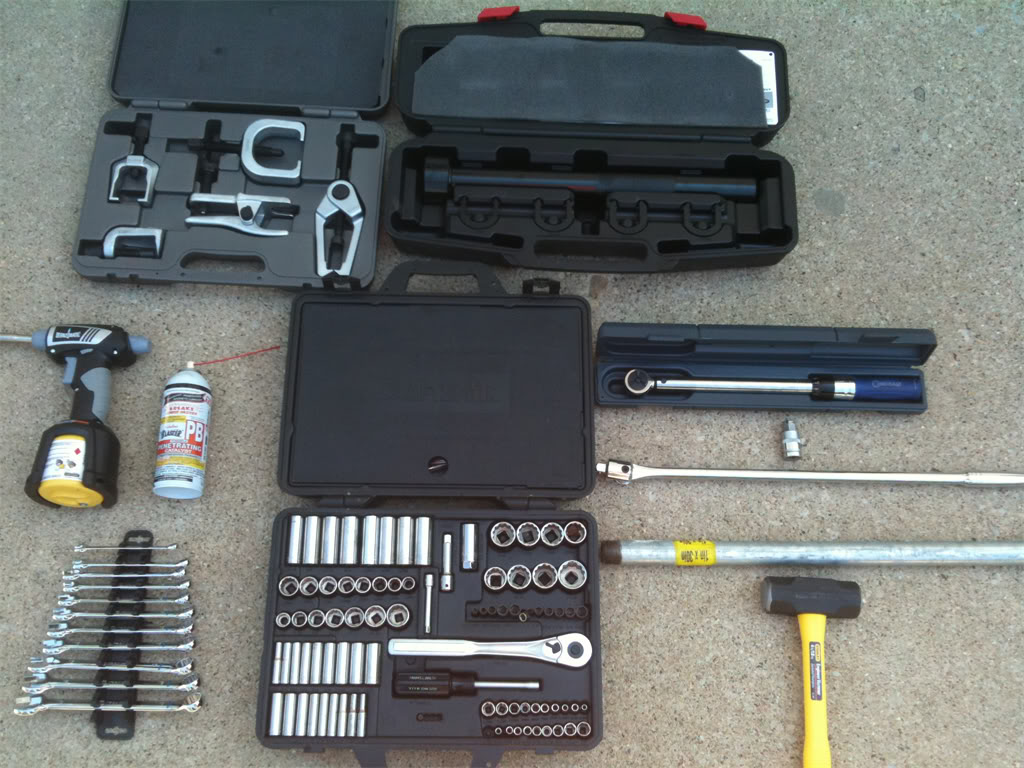
Alright, so let's begin. First of all, let's talk about the tools that will be needed for this job. Here's what I used:
Hex(Allen) sockets: 7mm, 10mm, 17mm(This one must be a 1/2" socket)
Box end wrenches: 13mm, 16mm, 17mm, 18mm, 22mm, 24mm(if using the front end service kit)
Ratchets: 1/4", 3/8" and 1/2"
Sockets: 10mm, 13mm, 16mm, 17mm, 18mm.
- 3/8" Torque wrench
- At least one adjustable wrench.
- 25" x 1/2" breaker bar
- 30" x 1" galvanized pipe, to use as an extension for the breaker bar.
- Short flathead screwdriver
- Set of various size punches
- Pry bar
- Carpenter's hammer
- 4lb sledgehammer
- Can of PB Blaster
- Large zip ties
- OTC Front End Service Kit
- Advance Auto Parts special rental kit #85 - Inner tie rod enter removal kit.
- Mapp gas torch
- Tire iron to remove the 17mm lugnuts from the wheels
- A good pair of impact resistant and chemical splash-proof goggles.
- LED headlamp for your head(invaluable when working on the inner tie rod ends. Nothin' like hands-free light!)
Here is a pic of most of the kit I used:
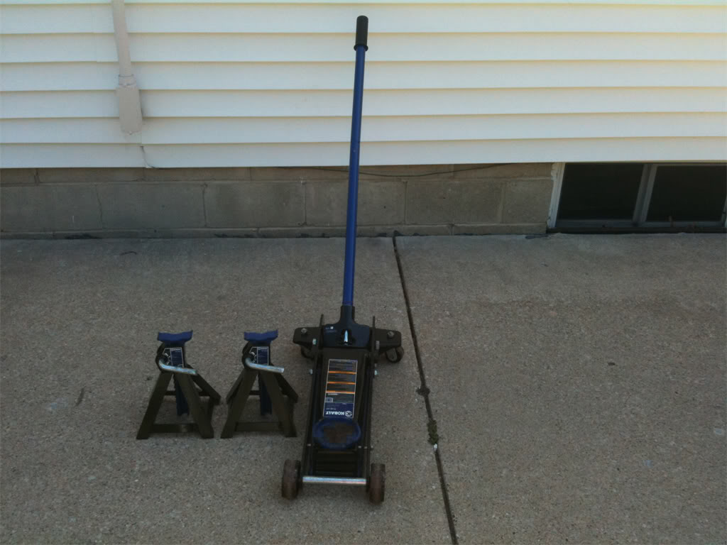
We'll also need a good jack and a couple of jack stands for safety!
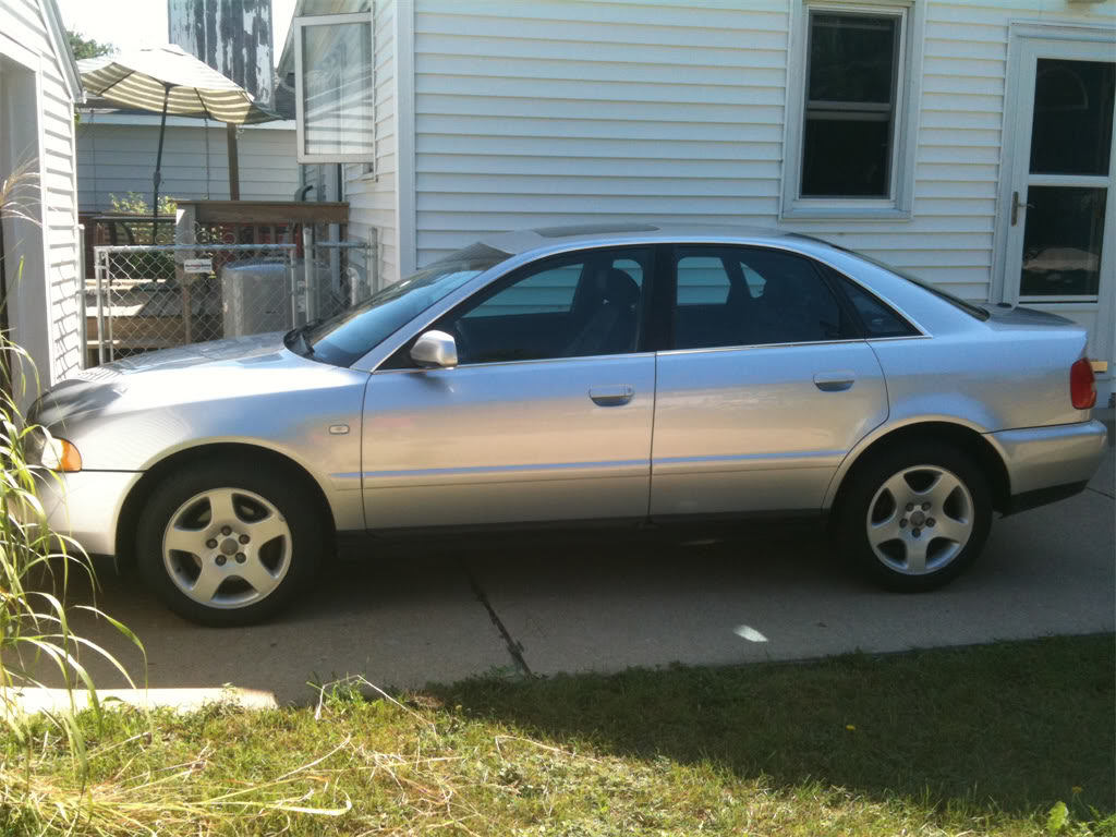
Here is my beloved 1999.5 Audi A4(Sexy wheel gap FTW! )
)
A few days before you begin this project, I strongly recommend spraying the nuts and bolts of the upper control arms, lower control arms and tie rod ends with PB Blaster so that you have a better chance of breaking them loose without snapping a bolt head off. I am speaking from experience, people. Trust me, you don't want to snap off a pinch bolt head if you can help it!")
Right, get yourself organized and let's do this!
There are two ways to do this job, one way is to remove the wheel bearing housing(also called the "spindle"). The other way, as you may have cleverly guessed, is to leave it mounted. Since I was planning to do a DIY writeup, I decided to do it both ways to see which way was easier. In the end, I didn't think either way was better than the other. If I had to do it over again, I probably would have left the spindle attached. Removing the spindle freed up room to work on the inner tie rod end assemblies, but having to deal with the removal of the spindle and the remounting of it, was kind of a PITA. If forced to give an opinion, I would say to leave the spindle alone unless you need to change the wheel bearings.
If you decide that you want to remove the spindle, start with step one. If leaving the spindle intact, you may start with step two.
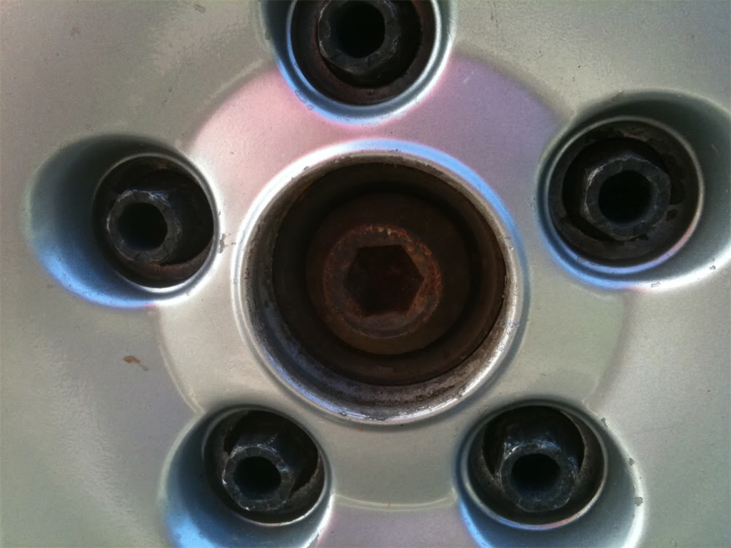
Step 1. To remove the wheel bearing housing(spindle), we first need to loosen the axle bolt while the car is still on the ground. This requires the use of the 17mm x 1/2" hex socket, the 1/2" breaker bar and the galvanized pipe. Remove the lugnut caps and center cap.
Here's what the 17mm hex socket looks like. It's a big one!
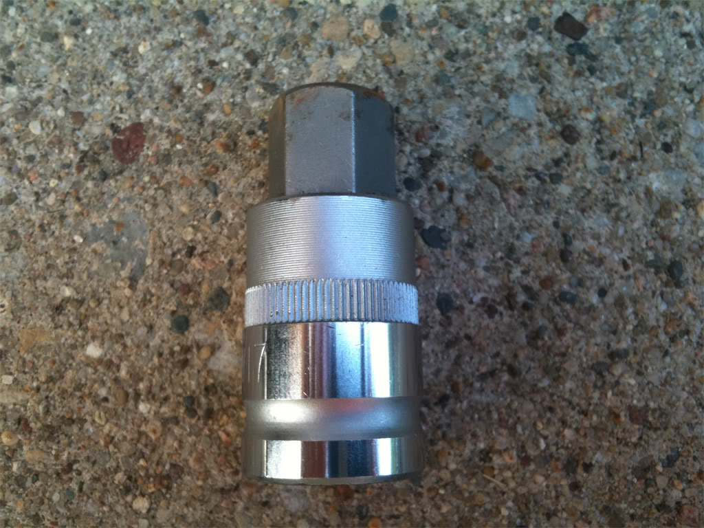
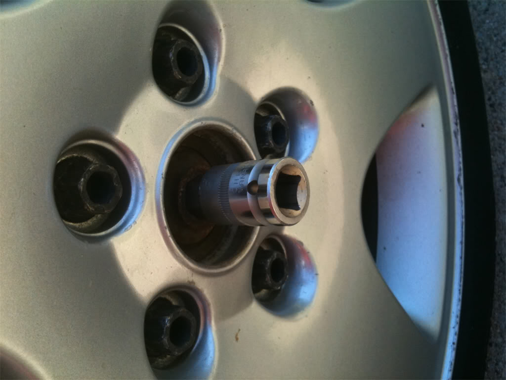
Step 2. Make sure that you insert the hex socket all the way into the axle bolt, otherwise it may slip while you're applying pressure to break it free. I used a hammer to lightly tap on the socket until it was fully-seated.
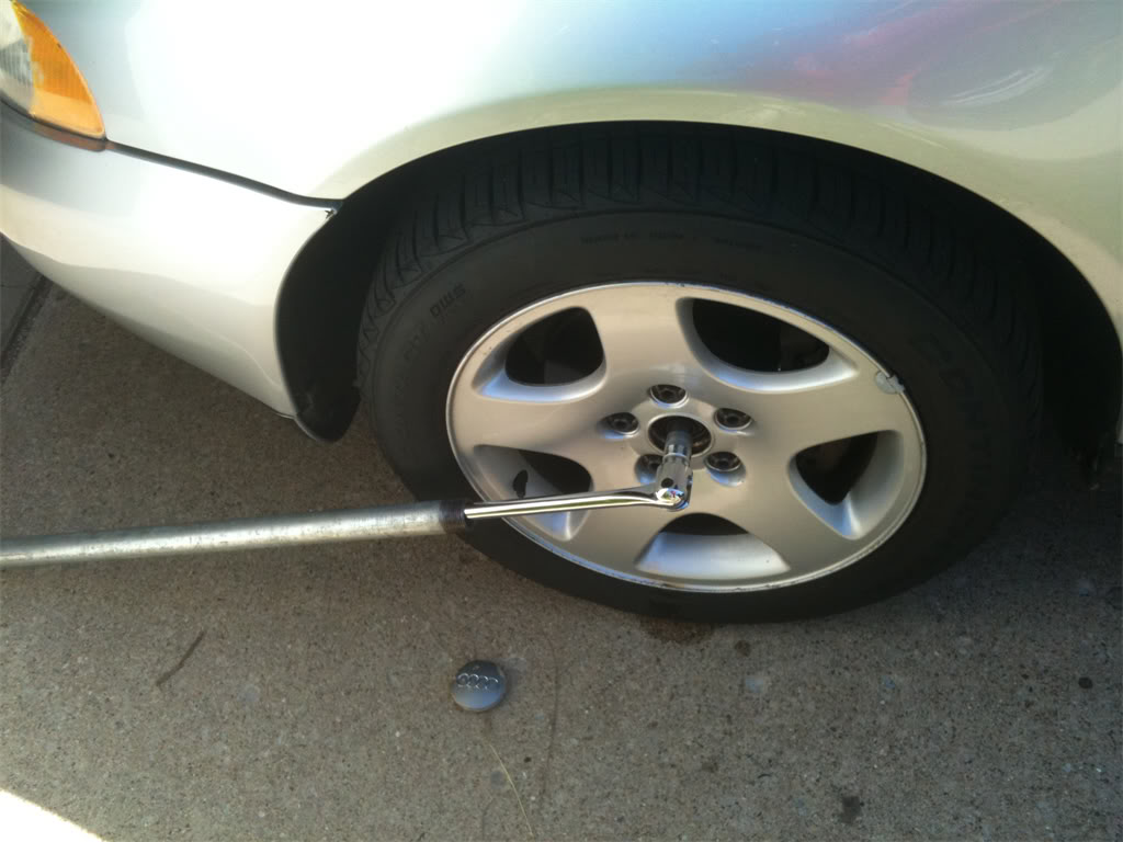
Step 3. Attach the socket to your breaker bar, then slip the 1" diameter galvanized pipe over the breaker bar. Remember, lefty-lucy. When you're ready, do your best Hulk Hogan impersonation and break that bolt loose! I said pull! It'll SNAP! when it breaks free. Whew, that took a bit of pressure. My back hurts already! This picture was taken after the snap. The original position of the bar & pipe was about 11:00.
Step 4. Now it's time to jack up the car and put it up on jack stands. Place the jack under the car and use your favorite spot to jack it up. I always use the sub frame shield as shown here.
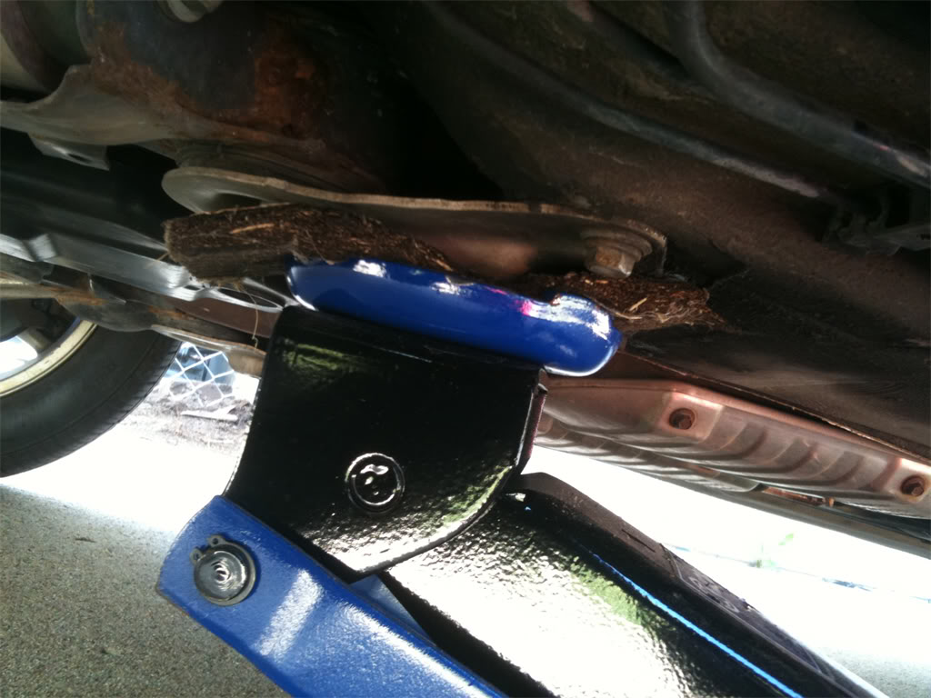
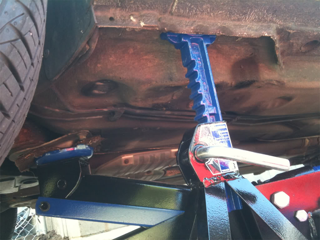
Step 5. Slide the jacks up under the car and then lower the car back down, making sure that both jack stands are on the same "notch" and are evenly handling the weight of the car. Here's a close up showing where I positioned the jack and the jack stand.
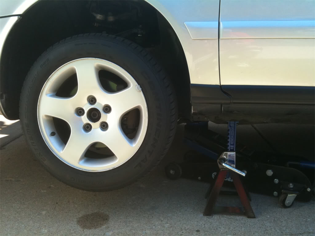
This is how the car looks when sitting on both jack stands.
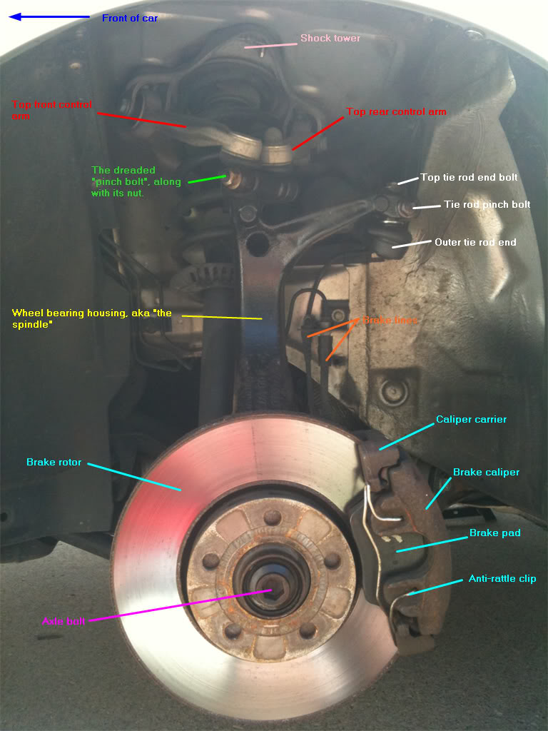
Step 6. Remove the 17mm lug nuts from each wheel, and then remove the wheel and set it aside. You will now be able to see the major parts of the front suspension and brake system. Notice how a nice shot of PB Blaster removed the rust look from the axle bolt. I was also surprised that my suspension was not more rusty than it was, considering that I live in the frozen tundra of Minnesota. This car has seen many winters worth of snow, ice and road salt.
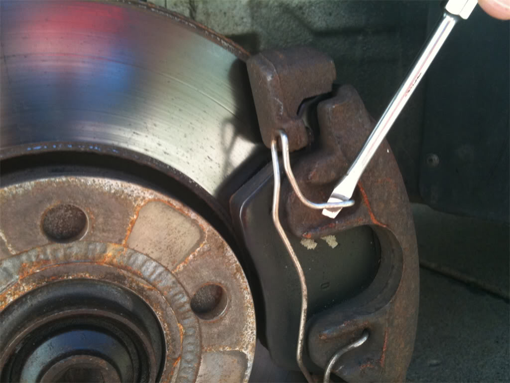
Step 7. Alright, lets get those brake parts off so that we have access to the lower control arms. First, we remove the anti-rattle clip from the caliper. A flat head screwdriver works well for this. Just pry it off carefully and set it aside.
Step 8. Next, we locate the two caliper bolts that reside in back of the rotor, hidden inside of rubber housings. Pop the caps off these housings with your flat head screwdriver.
Then insert the 7mm hex socket that's attached to your 3/8" ratchet. The pic below shows what it looks like with the socket already inside the bolt. Finally, remove both bolts.
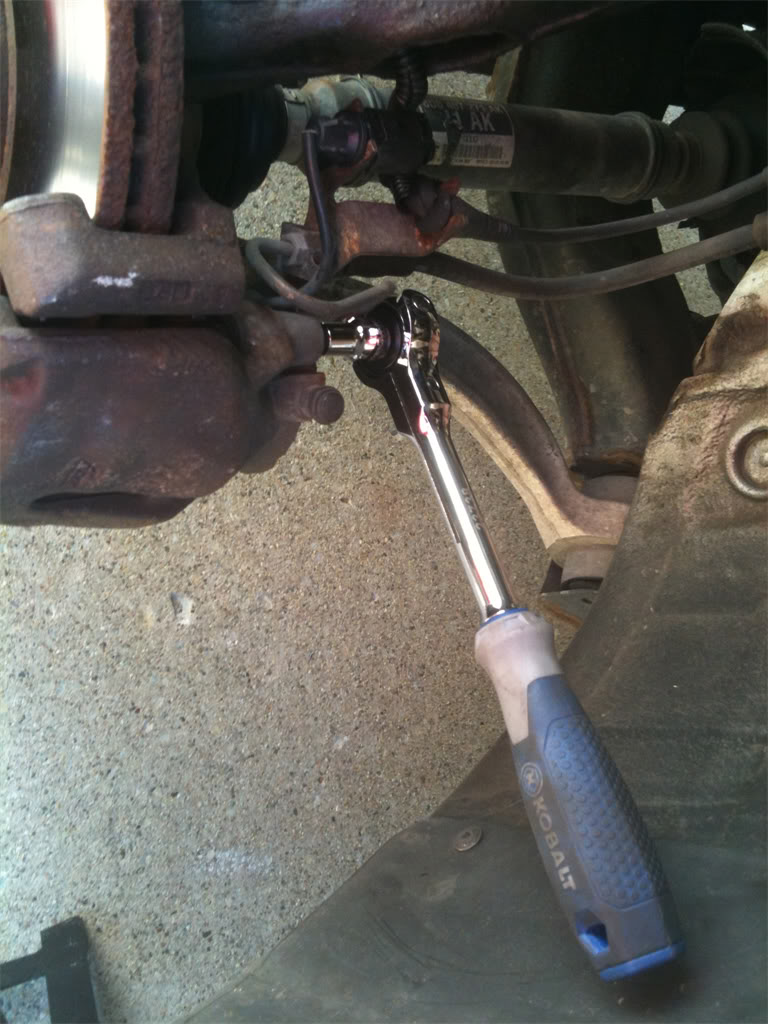
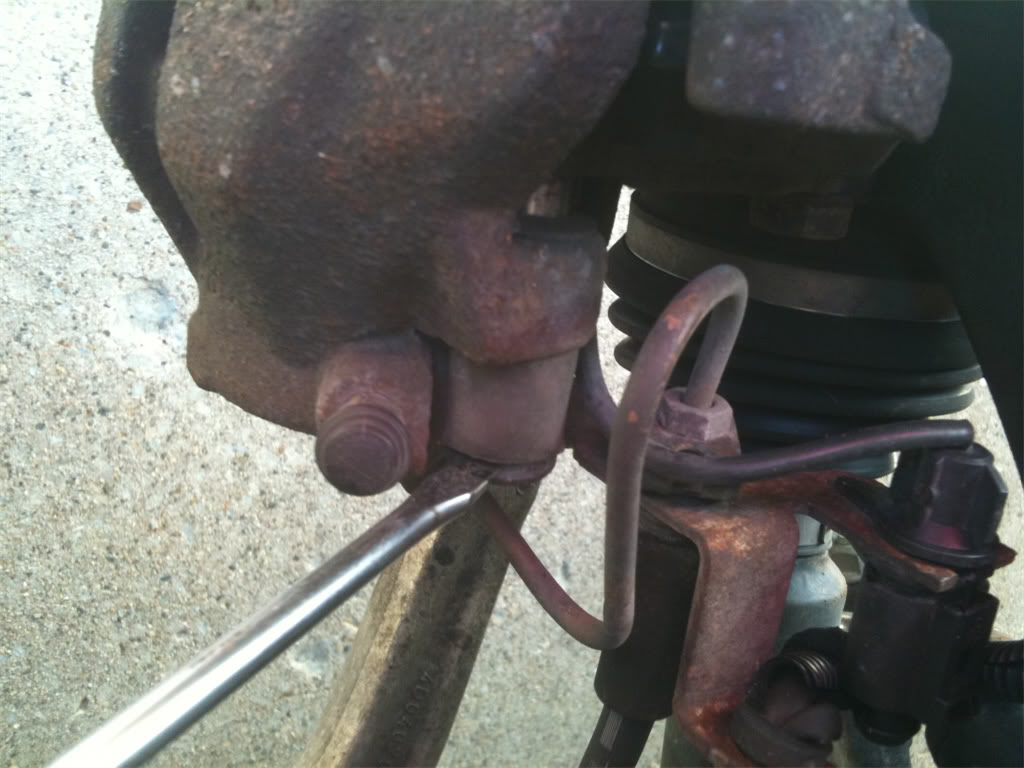
Step 9. With the bolts removed, you can carefully pull the caliper assembly off of the rotor & spindle. I had to insert a large flat head screwdriver into the slot on the caliper to help pry it off. When it's removed, either set it down on the lower control arm like this...
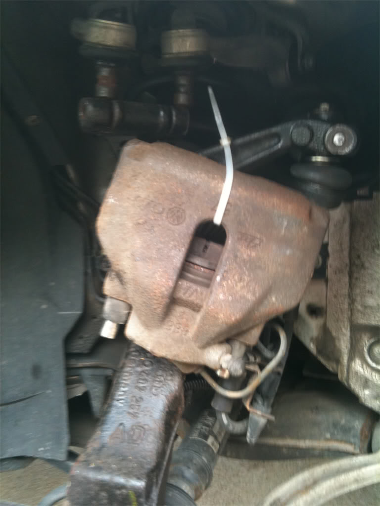
or hang it from the spindle using a large zip tie as shown here. Either way, the goal is to not stretch the rubber brake lines. DO NOT LET THE CALIPER HANG FROM THE BRAKE LINES!
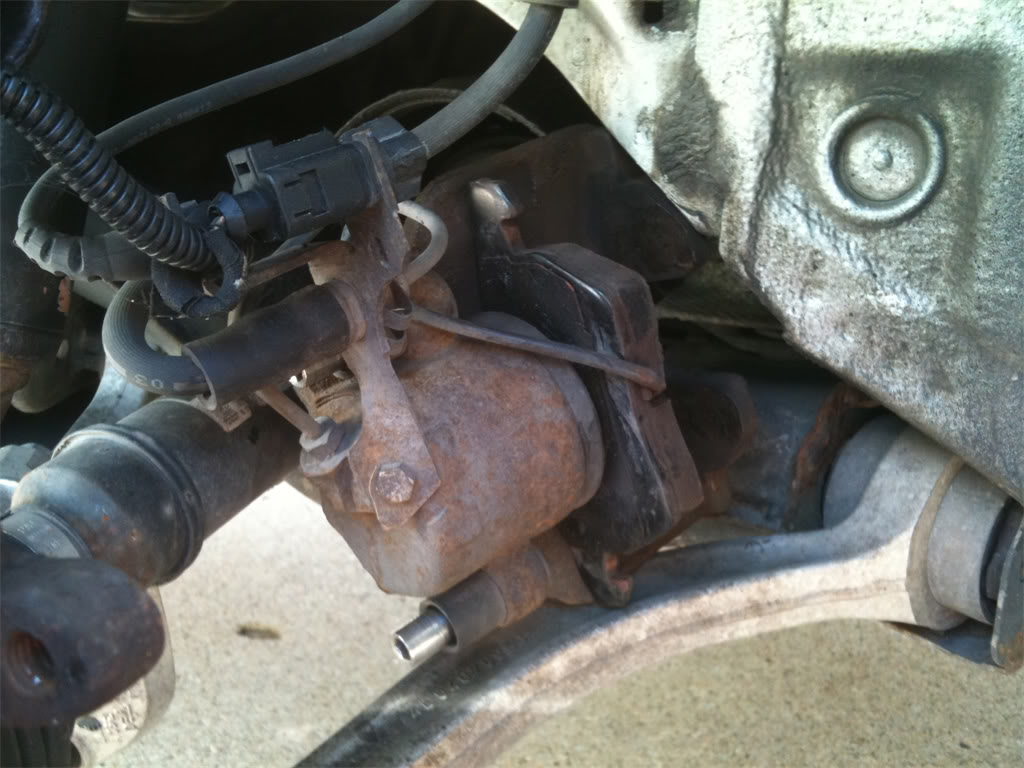
Step 10. Now that the caliper is removed, you'll want to remove the carrier. On the back side, find two very rusty 18mm bolts that you will spray with PB Blaster, and maybe even heat them up with the mapp gas torch before the attempt to break them free.
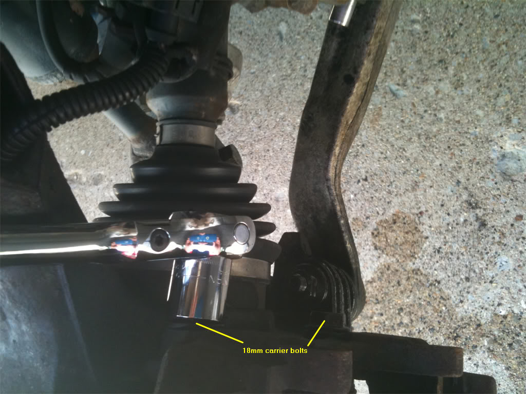
The idea here is to break free the bolts without breaking the bolts or the heads off the bolts. That's why it's always a good idea to let them soak in PB Blaster for a bit, or better yet, apply some mapp gas heat to them. Nothing breaks through rust like mapp gas heat. Alright then, remove the bolts, then set the carrier aside. Now you may remove the brake rotor from the spindle.
With the brake rotor removed, here's what you're left with.
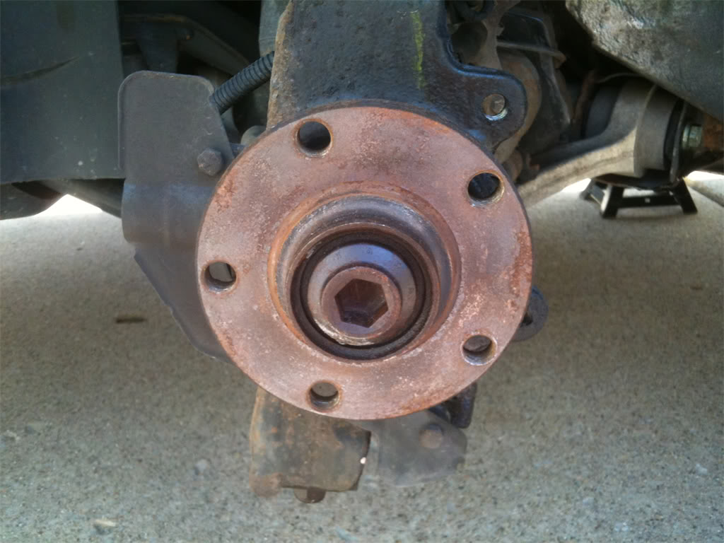
Great, you've got the brakes out of the way. Now you get to do what you came here for. Let's change out those old rotten tie rod end assemblies and control arms! Stay tuned for Part 2: Replacing the Inner and Outer Tie Rod End Assemblies.
This job was by far the most challenging one I've attempted on my B5, yet it went the smoothest of all the jobs I've done. While researching and preparing to do this job, all of the DIY's I found seemed to be tailored to the seasoned amateur mechanic, so I decided to do a DIY for those of us who have far less experience. All of the suggestions and advice I give here were given to me by others on this forum who are far more experienced than I am. In fact, I don't think I had an original thought in this whole series. All I did was take pictures and organize the great advice I got from others into this DIY.
I'm using so many pictures that I have to split this into multiple threads. I have therefore decided to split this into four parts:
1) Preparation
2) Replacing the Inner and Outer Tie Rod Assemblies
3) Replacing the Upper Control Arms
4) Replacing the Lower Control Arms
Alright, so let's begin. First of all, let's talk about the tools that will be needed for this job. Here's what I used:
Hex(Allen) sockets: 7mm, 10mm, 17mm(This one must be a 1/2" socket)
Box end wrenches: 13mm, 16mm, 17mm, 18mm, 22mm, 24mm(if using the front end service kit)
Ratchets: 1/4", 3/8" and 1/2"
Sockets: 10mm, 13mm, 16mm, 17mm, 18mm.
- 3/8" Torque wrench
- At least one adjustable wrench.
- 25" x 1/2" breaker bar
- 30" x 1" galvanized pipe, to use as an extension for the breaker bar.
- Short flathead screwdriver
- Set of various size punches
- Pry bar
- Carpenter's hammer
- 4lb sledgehammer
- Can of PB Blaster
- Large zip ties
- OTC Front End Service Kit
- Advance Auto Parts special rental kit #85 - Inner tie rod enter removal kit.
- Mapp gas torch
- Tire iron to remove the 17mm lugnuts from the wheels
- A good pair of impact resistant and chemical splash-proof goggles.
- LED headlamp for your head(invaluable when working on the inner tie rod ends. Nothin' like hands-free light!)
Here is a pic of most of the kit I used:
We'll also need a good jack and a couple of jack stands for safety!
Here is my beloved 1999.5 Audi A4(Sexy wheel gap FTW!
)A few days before you begin this project, I strongly recommend spraying the nuts and bolts of the upper control arms, lower control arms and tie rod ends with PB Blaster so that you have a better chance of breaking them loose without snapping a bolt head off. I am speaking from experience, people. Trust me, you don't want to snap off a pinch bolt head if you can help it!
Right, get yourself organized and let's do this!
There are two ways to do this job, one way is to remove the wheel bearing housing(also called the "spindle"). The other way, as you may have cleverly guessed, is to leave it mounted. Since I was planning to do a DIY writeup, I decided to do it both ways to see which way was easier. In the end, I didn't think either way was better than the other. If I had to do it over again, I probably would have left the spindle attached. Removing the spindle freed up room to work on the inner tie rod end assemblies, but having to deal with the removal of the spindle and the remounting of it, was kind of a PITA. If forced to give an opinion, I would say to leave the spindle alone unless you need to change the wheel bearings.
If you decide that you want to remove the spindle, start with step one. If leaving the spindle intact, you may start with step two.
Step 1. To remove the wheel bearing housing(spindle), we first need to loosen the axle bolt while the car is still on the ground. This requires the use of the 17mm x 1/2" hex socket, the 1/2" breaker bar and the galvanized pipe. Remove the lugnut caps and center cap.
Here's what the 17mm hex socket looks like. It's a big one!
Step 2. Make sure that you insert the hex socket all the way into the axle bolt, otherwise it may slip while you're applying pressure to break it free. I used a hammer to lightly tap on the socket until it was fully-seated.
Step 3. Attach the socket to your breaker bar, then slip the 1" diameter galvanized pipe over the breaker bar. Remember, lefty-lucy. When you're ready, do your best Hulk Hogan impersonation and break that bolt loose! I said pull! It'll SNAP! when it breaks free. Whew, that took a bit of pressure. My back hurts already! This picture was taken after the snap. The original position of the bar & pipe was about 11:00.
Step 4. Now it's time to jack up the car and put it up on jack stands. Place the jack under the car and use your favorite spot to jack it up. I always use the sub frame shield as shown here.
Step 5. Slide the jacks up under the car and then lower the car back down, making sure that both jack stands are on the same "notch" and are evenly handling the weight of the car. Here's a close up showing where I positioned the jack and the jack stand.
This is how the car looks when sitting on both jack stands.
Step 6. Remove the 17mm lug nuts from each wheel, and then remove the wheel and set it aside. You will now be able to see the major parts of the front suspension and brake system. Notice how a nice shot of PB Blaster removed the rust look from the axle bolt. I was also surprised that my suspension was not more rusty than it was, considering that I live in the frozen tundra of Minnesota. This car has seen many winters worth of snow, ice and road salt.
Step 7. Alright, lets get those brake parts off so that we have access to the lower control arms. First, we remove the anti-rattle clip from the caliper. A flat head screwdriver works well for this. Just pry it off carefully and set it aside.
Step 8. Next, we locate the two caliper bolts that reside in back of the rotor, hidden inside of rubber housings. Pop the caps off these housings with your flat head screwdriver.
Then insert the 7mm hex socket that's attached to your 3/8" ratchet. The pic below shows what it looks like with the socket already inside the bolt. Finally, remove both bolts.
Step 9. With the bolts removed, you can carefully pull the caliper assembly off of the rotor & spindle. I had to insert a large flat head screwdriver into the slot on the caliper to help pry it off. When it's removed, either set it down on the lower control arm like this...
or hang it from the spindle using a large zip tie as shown here. Either way, the goal is to not stretch the rubber brake lines. DO NOT LET THE CALIPER HANG FROM THE BRAKE LINES!
Step 10. Now that the caliper is removed, you'll want to remove the carrier. On the back side, find two very rusty 18mm bolts that you will spray with PB Blaster, and maybe even heat them up with the mapp gas torch before the attempt to break them free.
The idea here is to break free the bolts without breaking the bolts or the heads off the bolts. That's why it's always a good idea to let them soak in PB Blaster for a bit, or better yet, apply some mapp gas heat to them. Nothing breaks through rust like mapp gas heat. Alright then, remove the bolts, then set the carrier aside. Now you may remove the brake rotor from the spindle.
With the brake rotor removed, here's what you're left with.
Great, you've got the brakes out of the way. Now you get to do what you came here for. Let's change out those old rotten tie rod end assemblies and control arms! Stay tuned for Part 2: Replacing the Inner and Outer Tie Rod End Assemblies.
Last edited by jdahlen24; 08-25-2011 at 09:16 PM.

#3
08-25-2011, 06:01 PM
Thanks, Beau. Jeremy said that he would sticky these when he drops by. I hope someone finds this series useful. It's my way of giving back to the community for all the great advice and help over the past year.
#4
08-25-2011, 06:44 PM
Holy **** man, I'm reading these in order and I have to say that so far it's probably the most comprehensive DIY I've ever seen. Excellent, excellent work. I'll move them all to the DIY forum for permanency. I'm not going to merge them into one thread as one part or another may be useful to someone during a job, but I'll link each installment to the previous and the next via clickable link so someone using the whole thing can jump readily and easily.
#5
08-25-2011, 08:32 PM
Should have read ^that^ before I posted in the other thread lol. Outstanding work man!!! Only thing I would like to add to this section is for the love of God and all things holy, DO NOT USE THE WIDOWMAKER FOR THIS JOB. Get a proper jack and some jack stands pleeeease.
#6
08-25-2011, 08:57 PM
No kidding. The force required to loosen any of the nuts/bolts is enough to lean a widowmaker and drop the car right onto the person wrenching on it. Beg, borrow, or steal some real gear.

Thread
Thread Starter
Forum
Replies
Last Post
jdahlen24
DIY - Do It Yourself
5
08-25-2011 09:50 PM
jdahlen24
DIY - Do It Yourself
0
08-25-2011 03:05 PM
jdahlen24
DIY - Do It Yourself
0
08-25-2011 12:49 PM