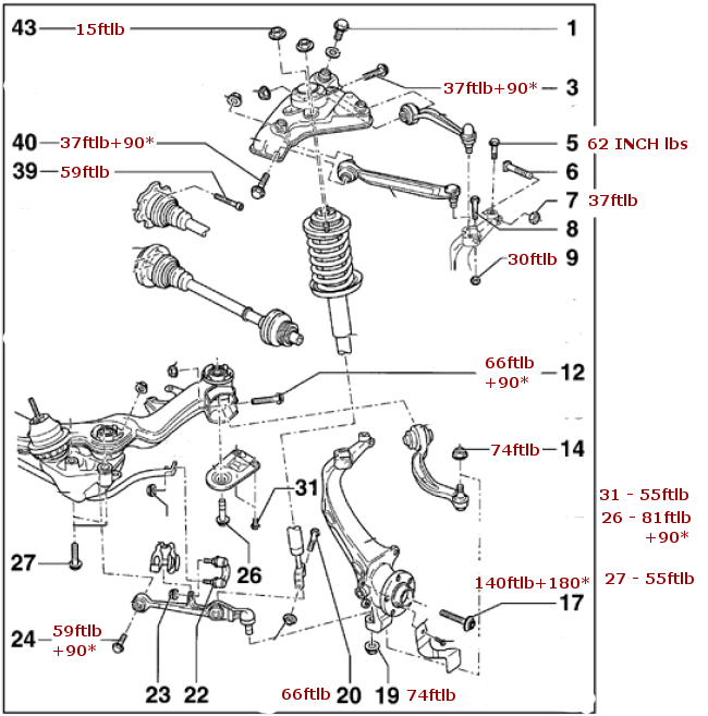
B5 Front suspension diagram including all torque values
#1
 07-09-2012, 01:55 PM


I made this in anticipation of installing my control arm kit. Hope others find it useful. It's for my B5.5 A4 2.8 Quattro Avant
3 Tower bolts - 48ftlb/55ftlb
note* there's a conflict in the bentley re: the tower bolts. The exploded suspension diagram says 55ftlb but the "Mounting bracket, removing and installing" section says 48ftlb
Special note for (23)
Rubber bushing style link - 30ftlb+90* for upper and lower
Ball joint style link - 30ftlb+90* at control arm and 74ftlb at Stab bar
I grabbed these from the bentley and it's what I'll use and of course this is only to illustrate how I'm doing it
Last edited by savantv; 07-09-2012 at 02:00 PM. Reason: added embedded image/spelling
#4
07-11-2012, 12:11 PM
I tried to add this to my exploded suspension and torques post but it was locked...
For stock heights in stead of "setting it where the old ones were" you can use this spec
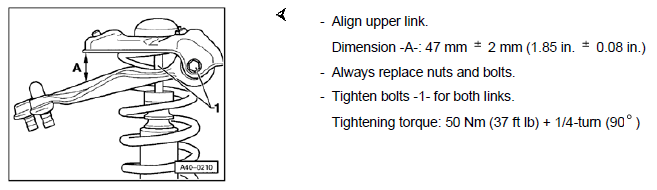
For stock heights in stead of "setting it where the old ones were" you can use this spec
#6
07-11-2012, 01:51 PM

One note about this, though I'm not sure how critical it is: the upper CAs have inner bushings which don't pivot when the suspension cycles; the bushings only flex (this is why they have to be set a certain way). It's good you noted that the upper CAs should be oriented in that fashion for "stock heights" because when a car is lowered, the upper CA inner bolts/bushings could be re-oriented to match the new ride height.
Generally it is essential to torque the lower CA mounting bolts only when the suspension is compressed to the new ride height because that will maximize bushing longevity. I doubt that torquing the upper CA inner bushings in that fashion is nearly as critical because those bushings don't take much of a load compared to the lower CA bushings.
Generally it is essential to torque the lower CA mounting bolts only when the suspension is compressed to the new ride height because that will maximize bushing longevity. I doubt that torquing the upper CA inner bushings in that fashion is nearly as critical because those bushings don't take much of a load compared to the lower CA bushings.
#7
07-11-2012, 09:43 PM
Ok, both the diagram threads are merged and part of the DIY forum. Once again, thank you Savantv for kicking some more ***. Keep this stuff coming anytime you feel like it

Thread
Thread Starter
Forum
Replies
Last Post
JDV
Audi A6
1
04-03-2005 07:40 PM