
B5 1.8T Engine Diagrahm


Thread Starter
|
1st Gear
Joined: Jul 2006
Posts: 91
From:
So, the previous version of this diagrahm I have is labeled all wrong, so I was trying to get this filled out right, i'll start it with the easy ones I know and hopefully with everyone's input, it can be complete (and correct) shortly. Thanks.[/align]

3)
4) 058 Check Valve
5) Airbox
6) K03 Turbo
7)
8)
9)
10) 058 Check Valve
11)
12) 058 Check Value
13)
14)
15) 058 Check Valves
16)
17) Intercooler
18)
19)
20) Intake Manifold
21)
22)
23) Diverter Valve
24)[/align]
3)
4) 058 Check Valve
5) Airbox
6) K03 Turbo
7)
8)
9)
10) 058 Check Valve
11)
12) 058 Check Value
13)
14)
15) 058 Check Valves
16)
17) Intercooler
18)
19)
20) Intake Manifold
21)
22)
23) Diverter Valve
24)[/align]


1st Gear
Joined: Mar 2006
Posts: 258
From:
Ok, I found my Bentley manual page (for B6, I'll match up to your B5 diagram best I can)
Thing on the far left (unnumbered and cut off in your diagram) is the secondary air injection pump
3-EVAP purge valve (N80)
7-Combination valve for secondary air injection
9-Goes to brake booster
13-Secondary Air Injection Solenoid Valve
18-To EVAP leak detection pump
19-Recirculating valve for turbo
21-Vacuum diaphragm for boost pressure regulation
22-N75 (Wastegate Bypass Regulator Valve)
23-DV
24-Pressure regulator valve for crankshaft housing ventilation
Thread Starter
|
1st Gear
Joined: Jul 2006
Posts: 91
From:
Finished Version...if anyone is interested:
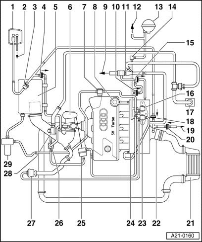
1)[/b] EVAP canister
2)[/b] From fuel tank
3)[/b] Evaporative Emission (EVAP) canister purge regulator valve (N80)
4)[/b] Check-valve for EVAP canister (between EVAP canister and intake manifold before turbocharger)
- Installation position (light/dark side): Arrow points in direction of flow, as shown[/i] -
5)[/b] Air Box/Intake
6)[/b] Turbocharger (Check boost pressure page 21-46)
7)[/b] Combination valve for secondary air injection (AIR)
8)[/b] Fuel pressure regulator (FPR)
9)[/b] To power brake booster
10)[/b] 058 Check valve
- Installation position (light/dark side): Arrow points in direction of flow, as shown[/i] -
11)[/b] Vacuum booster
12)[/b] To Leak Detection Pump (LDP)
13)[/b] Vacuum reservoir
14)[/b] Distributor piece
15)[/b] 058 Check valve
- Installation position (light/dark side): Arrow points in direction of flow, as shown[/i] -
16)[/b] Secondary Air Injection (AIR) solenoid valve (N112)
17)[/b] Crankcase vent
18)[/b] 058 Check valve
Installation position (light/dark side): Arrow points in direction of flow, as shown
19)[/b] To tank Leak Detection Pump (LDP) (V144)
20)[/b] 058 Check valve
- Installation position (light/dark side): Arrow points in direction of flow, as shown[/i] -
21)[/b] Intercooler w/charge air pressure sensor (G31)
22)[/b] Throttle Body (valve control module) (J338)
23)[/b] Reticulating valve for turbocharger (N249)
24)[/b] Intake manifold w/Intake Air Temperature (IAT) sensor (G42)
25)[/b] Pressure unit for boost pressure regulation (Wastegate Actuator?)
26)[/b] Wastegate bypass regulator valve (N75)
27)[/b] Mechanical recirculation valve
28)[/b] Pressure control valve for crankcase ventilation (Crankcase Breather)
29)[/b] Secondary Air Injection (AIR) pump motor (V101)

