Diode Mod DIY (all wire color friendly)
#1
 06-02-2012, 06:25 PM


Ok, this DIY is another diode mod DIY but this one will work reguardless of what wire colors you have. May even work for those guys who's map sensor works with something other than 5v... or at least it'll let you know the range it works on and let you figure out what diode to use from there.
For those of you who are reading this wondering what this is for... it lets you run more boost without having your car freak out. Your car has a set limit it wants to see for boost and if it sees more than that it'll put an end to it one way or another. I have a big turbo setup with all the valves and whatnot taken out that it uses to control boost and it still stops me by simply slamming the throttle plate closed. Also being BT, I'm not 100% sure how this works with factory turbos. I know it works, but you may need a manual boost controler to control the boost, which is inexpensive, or it may not need one since the car doesn't know it's overboosting. Not sure.
There are already DIYs on this though and I know they discuss all that. I do know for sure though you're going to want vag-com to log air to fuel ratios and timing corrections if you're upping the boost. My car leaned out pretty bad pretty fast with a 4.3v diode for example, and that spells disaster. But again, I'm BT so I'm not sure that it would with a k03/04. Ok, moving along...
SEE BOTTOM FOR NOTES/ITEMS NEEDED
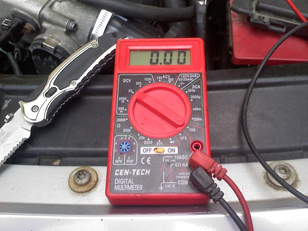
Step 1: Get a multimeter. They are inexpensive and come in way handy anytime you are doing any kind of electrical stuff. They can be found in the electrical section at wal-mart back by automotive. Should look similar to this:
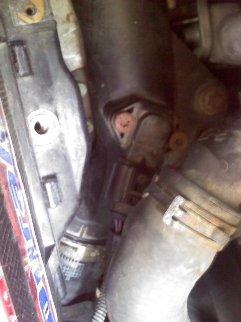
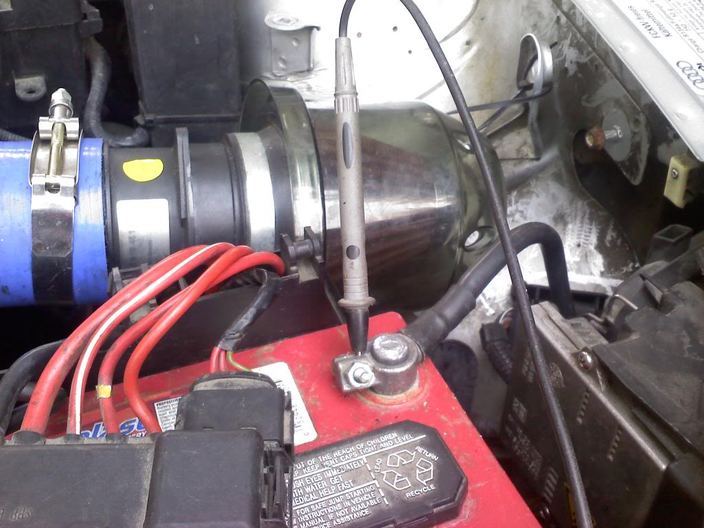
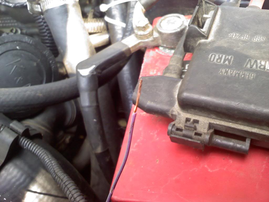
Step 2: Find your MAP sensor. I have a 2001 Audi TT 225, and it's right in front of the battery on the plastic pipe between the intercooler and the rubber hose going to the throttle body. It should look like this:
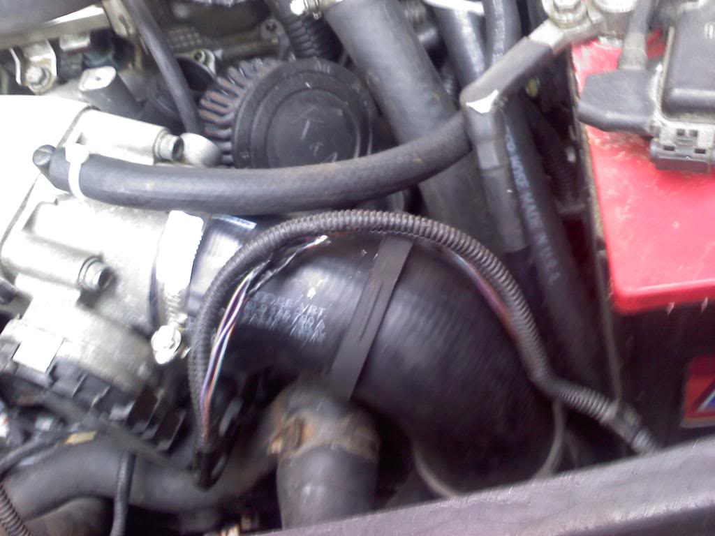
Step 3: Follow the wiring loom and pull the wires out of it somewhere easy to work with. I pulled mine out right up top as shown:
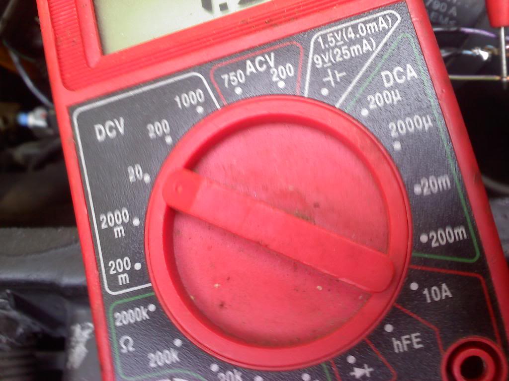
Step 4: Set your multimeter to 20 under DCV. That is for direct current volts and 20 is the accuracy of the decimal place if you must know.
Step 5: Put the ground probe (black) of the multimeter to ground on your battery.
Step 6: Use a kife like I did or a set of wire strippers or whatever to strip back a section of insulation on each wire so that you can probe the bare wire with your positive probe. One wire should read about 5v:
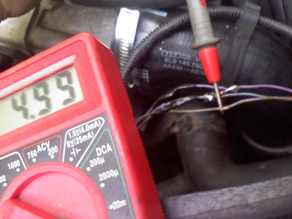
This wire is the power to the sensor. You do not need this wire, so take note of the colors and ignore it.
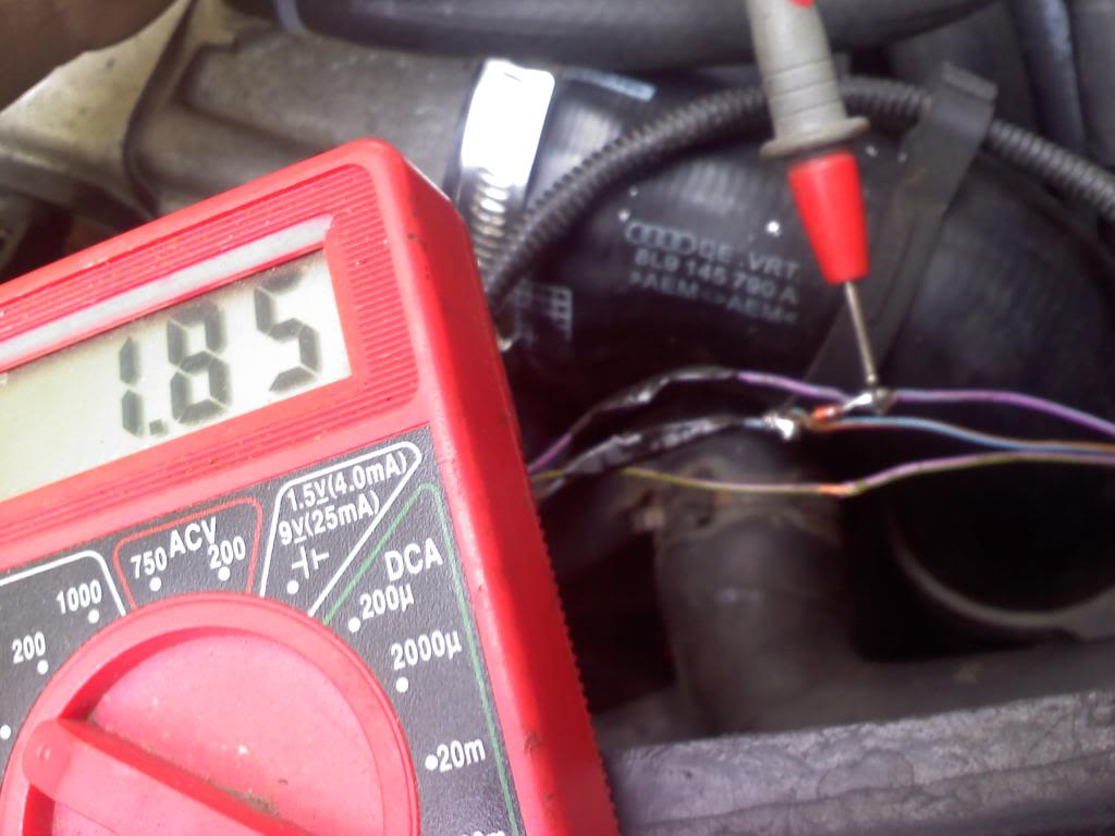
Another wire should read about 2v... I'm sure this is going to vary depending on altitude. This is your signal wire.
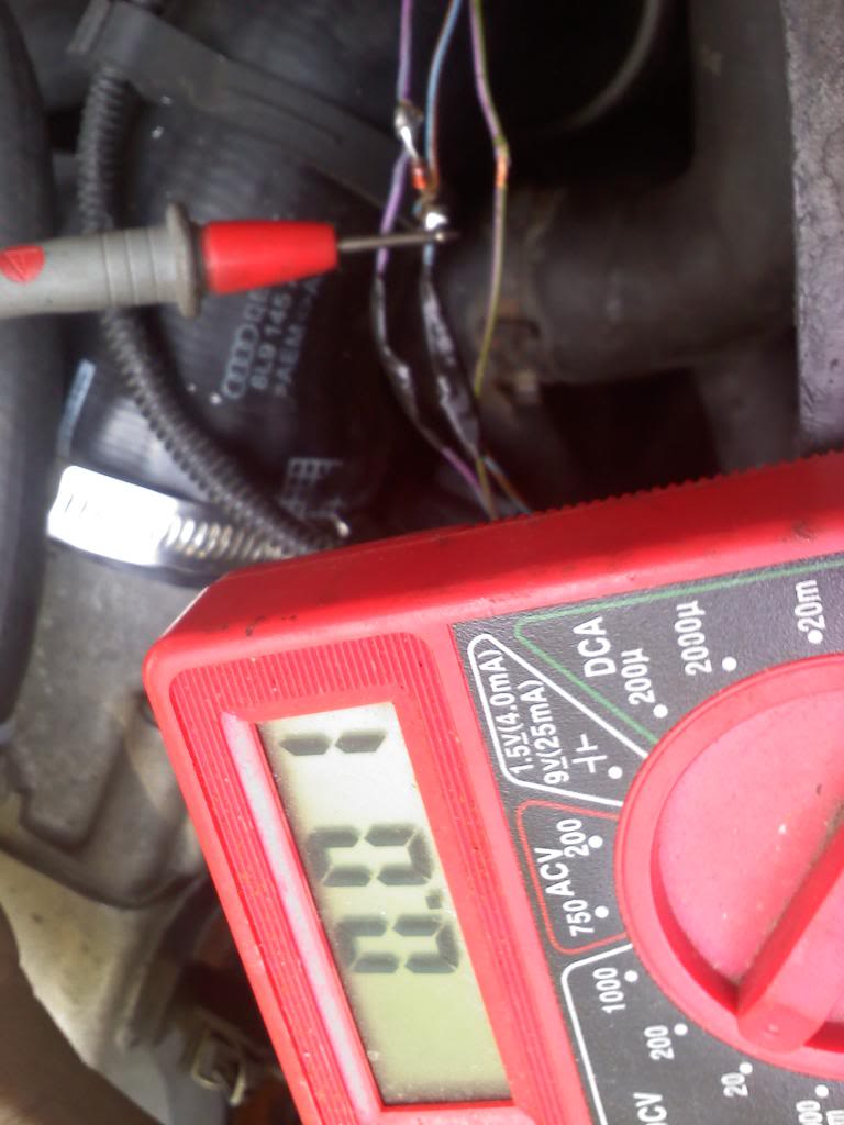
The last wire shouldn't read anything as it is the ground for the sensor. You should get a reading something like this:
Now you know for sure what wires you are working with! If it makes you feel better you can put your red test probe to + on the battery and use the black probe to probe the said ground wire. It should read between 12 and 13v depending on how old your battery is.
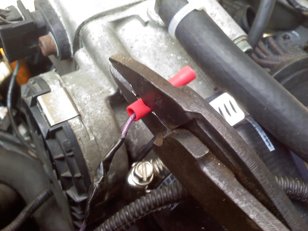
Step 7: Cut both the signal and ground wires and strip some insulation off both ends that you have made. I'd say about 1/4"-3/8" on one side (just enough to put a butt connector on) and about 3/4" on the other side for each wire.
Step 8: Crimp the butt connector on the 1/4" stripped side of each wire.
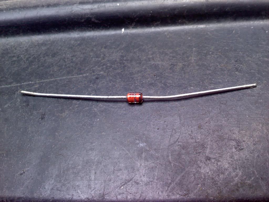
Step 9: Identify which side of your diode has the stripe on it. As you can (hopefully) see, there is a black stripe on the right side of this diode:
Step 10: Bend the diode into a "U" shape and then wrap the signal wire around the stripe side of the diode. Cut off the excess wire from the diode so that it's flush.
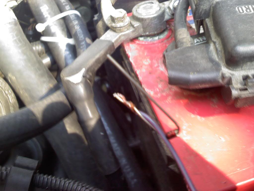
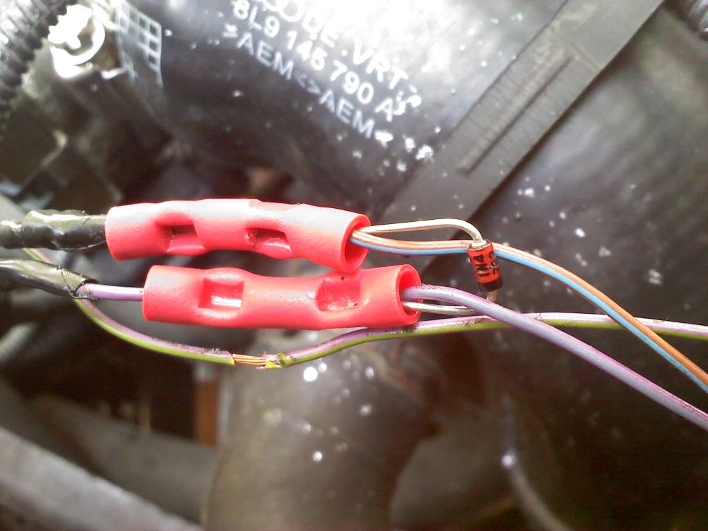
Step 11: Slide the twisted wire/diode into the open end of your butt connector on the signal wire and crimp it down, then repeat all of this for the ground
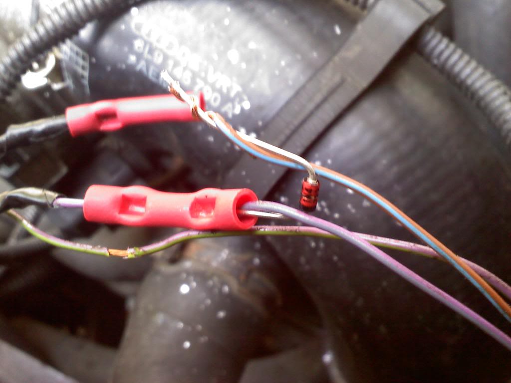
This is the installed diode!:
Step 12: Tape everything up all nice, tape each wire individually and then the whole cluster. Just make sure nothing can touch, most noteably the exposed diode wires.
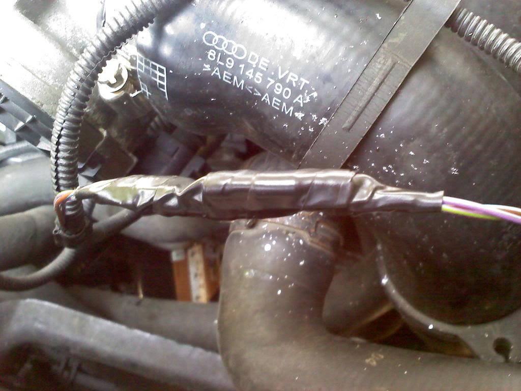
Then, put everything back in the wire loom and re-secure the wire with zip ites or however you need to . Make sure it's away from your fans on the radiator. Now crank up the boost! Actually, do it slowly, like 1 psi at a time and log everything each time watching for timing CRs under 6-7 and good air to fuel ratios. Be smart and know exactly what you're doing... you can definately have serious problems if you go crazy with the boost.
Notes: Like I said above, there is already plenty of DIYs on this, the one I found most helpful when doing mine was this one. There they show the diode being installed with a switch for some reason and there is much more discussion on what effects it has on a factory turbo. I know for chipped cars 4.7v diode is used and on a stock setup a 4.3v diode is used. However, I have stock programming and use a 4.7 and it doesn't seem to be a problem. MAKE SURE you use a 5 watt diode though. Similar to this one.. The diode in the pics in this DIY will burn out on you eventually. You need a bigger one. Since the 5w I have had 0 problems. I also do not recommend soldering your diode in considering I have changed this diode out a couple times, once for the 4.3 being too small and leaning out my car (again, I'm BT so it may not be an issue for you) and another it was in backwards (which, the car still starts... even though in the other forum it says that's how you'll know if it's in backwards) and another time for some reason. However the trial end error is done for you lol, so you may be able to just solder it in lol. But it made taking it out and switching them a nightmare for me.
I'm sure there is more to this DIY that I should have included, but this is 99% of it. I'm sure someone totally new to this will have a question I didn't think of or wasn't addressed in the other thread, and in that case just ask!
PARTS LIST:
Miltimeter - walmart should be under $10
Butt connectors - walmart again probably like $3
5w diode (4.3v or 4.7v depending on application) - $3 on ebay
wire strippers / crimpers - walmart, should be under $10
electrical tape - walmart... not sure $wise but it's cheap lol
all this stuff at walmart is all in the electrical section by automotive
For those of you who are reading this wondering what this is for... it lets you run more boost without having your car freak out. Your car has a set limit it wants to see for boost and if it sees more than that it'll put an end to it one way or another. I have a big turbo setup with all the valves and whatnot taken out that it uses to control boost and it still stops me by simply slamming the throttle plate closed. Also being BT, I'm not 100% sure how this works with factory turbos. I know it works, but you may need a manual boost controler to control the boost, which is inexpensive, or it may not need one since the car doesn't know it's overboosting. Not sure.
There are already DIYs on this though and I know they discuss all that. I do know for sure though you're going to want vag-com to log air to fuel ratios and timing corrections if you're upping the boost. My car leaned out pretty bad pretty fast with a 4.3v diode for example, and that spells disaster. But again, I'm BT so I'm not sure that it would with a k03/04. Ok, moving along...
SEE BOTTOM FOR NOTES/ITEMS NEEDED
Step 1: Get a multimeter. They are inexpensive and come in way handy anytime you are doing any kind of electrical stuff. They can be found in the electrical section at wal-mart back by automotive. Should look similar to this:
Step 2: Find your MAP sensor. I have a 2001 Audi TT 225, and it's right in front of the battery on the plastic pipe between the intercooler and the rubber hose going to the throttle body. It should look like this:
Step 3: Follow the wiring loom and pull the wires out of it somewhere easy to work with. I pulled mine out right up top as shown:
Step 4: Set your multimeter to 20 under DCV. That is for direct current volts and 20 is the accuracy of the decimal place if you must know.
Step 5: Put the ground probe (black) of the multimeter to ground on your battery.
Step 6: Use a kife like I did or a set of wire strippers or whatever to strip back a section of insulation on each wire so that you can probe the bare wire with your positive probe. One wire should read about 5v:
This wire is the power to the sensor. You do not need this wire, so take note of the colors and ignore it.
Another wire should read about 2v... I'm sure this is going to vary depending on altitude. This is your signal wire.
The last wire shouldn't read anything as it is the ground for the sensor. You should get a reading something like this:
Now you know for sure what wires you are working with! If it makes you feel better you can put your red test probe to + on the battery and use the black probe to probe the said ground wire. It should read between 12 and 13v depending on how old your battery is.
Step 7: Cut both the signal and ground wires and strip some insulation off both ends that you have made. I'd say about 1/4"-3/8" on one side (just enough to put a butt connector on) and about 3/4" on the other side for each wire.
Step 8: Crimp the butt connector on the 1/4" stripped side of each wire.
Step 9: Identify which side of your diode has the stripe on it. As you can (hopefully) see, there is a black stripe on the right side of this diode:
Step 10: Bend the diode into a "U" shape and then wrap the signal wire around the stripe side of the diode. Cut off the excess wire from the diode so that it's flush.
Step 11: Slide the twisted wire/diode into the open end of your butt connector on the signal wire and crimp it down, then repeat all of this for the ground
This is the installed diode!:
Step 12: Tape everything up all nice, tape each wire individually and then the whole cluster. Just make sure nothing can touch, most noteably the exposed diode wires.
Then, put everything back in the wire loom and re-secure the wire with zip ites or however you need to . Make sure it's away from your fans on the radiator. Now crank up the boost! Actually, do it slowly, like 1 psi at a time and log everything each time watching for timing CRs under 6-7 and good air to fuel ratios. Be smart and know exactly what you're doing... you can definately have serious problems if you go crazy with the boost.
Notes: Like I said above, there is already plenty of DIYs on this, the one I found most helpful when doing mine was this one. There they show the diode being installed with a switch for some reason and there is much more discussion on what effects it has on a factory turbo. I know for chipped cars 4.7v diode is used and on a stock setup a 4.3v diode is used. However, I have stock programming and use a 4.7 and it doesn't seem to be a problem. MAKE SURE you use a 5 watt diode though. Similar to this one.. The diode in the pics in this DIY will burn out on you eventually. You need a bigger one. Since the 5w I have had 0 problems. I also do not recommend soldering your diode in considering I have changed this diode out a couple times, once for the 4.3 being too small and leaning out my car (again, I'm BT so it may not be an issue for you) and another it was in backwards (which, the car still starts... even though in the other forum it says that's how you'll know if it's in backwards) and another time for some reason. However the trial end error is done for you lol, so you may be able to just solder it in lol. But it made taking it out and switching them a nightmare for me.
I'm sure there is more to this DIY that I should have included, but this is 99% of it. I'm sure someone totally new to this will have a question I didn't think of or wasn't addressed in the other thread, and in that case just ask!
PARTS LIST:
Miltimeter - walmart should be under $10
Butt connectors - walmart again probably like $3
5w diode (4.3v or 4.7v depending on application) - $3 on ebay
wire strippers / crimpers - walmart, should be under $10
electrical tape - walmart... not sure $wise but it's cheap lol
all this stuff at walmart is all in the electrical section by automotive

Thread
Thread Starter
Forum
Replies
Last Post