DIY: B5 Control Arms and Tie Rod End Assemblies, Part 4: Lower Control Arms
#1
 08-25-2011, 05:53 PM

In the final part of this series, you will remove and replace the lower control arms and tie rod ends.
We're in the home stretch, so let's do it!
Way back in part 1, I gave you the option of leaving the wheel bearing housing(aka "the spindle") alone, or removing it. If you decided that you wanted to remove it to replace the front wheel bearings, or if you just want more room to maneuver while changing everything else out, continue to step 27. Those of you who decided to leave the spindle alone can skip ahead to step 29.
Step 27. To remove the axle from the spindle, turn the axle bolt counter clockwise a few turns, then push it in with both thumbs while holding onto the spindle with the rest of your fingers. Using this method, continue to work the axle out of the housing until you can no longer move the axle with the axle bolt. You may then remove the axle bolt and place it somewhere where it won't get dirty or contaminated with anything.
Looking into the hole where the axle bolt was, this is what we see:
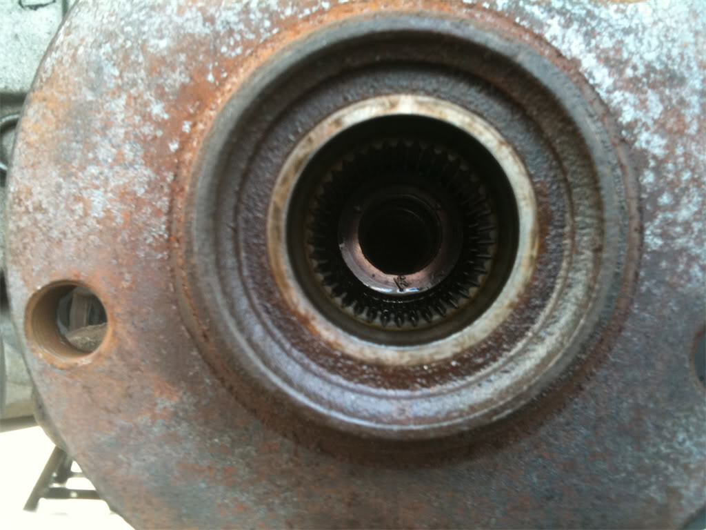
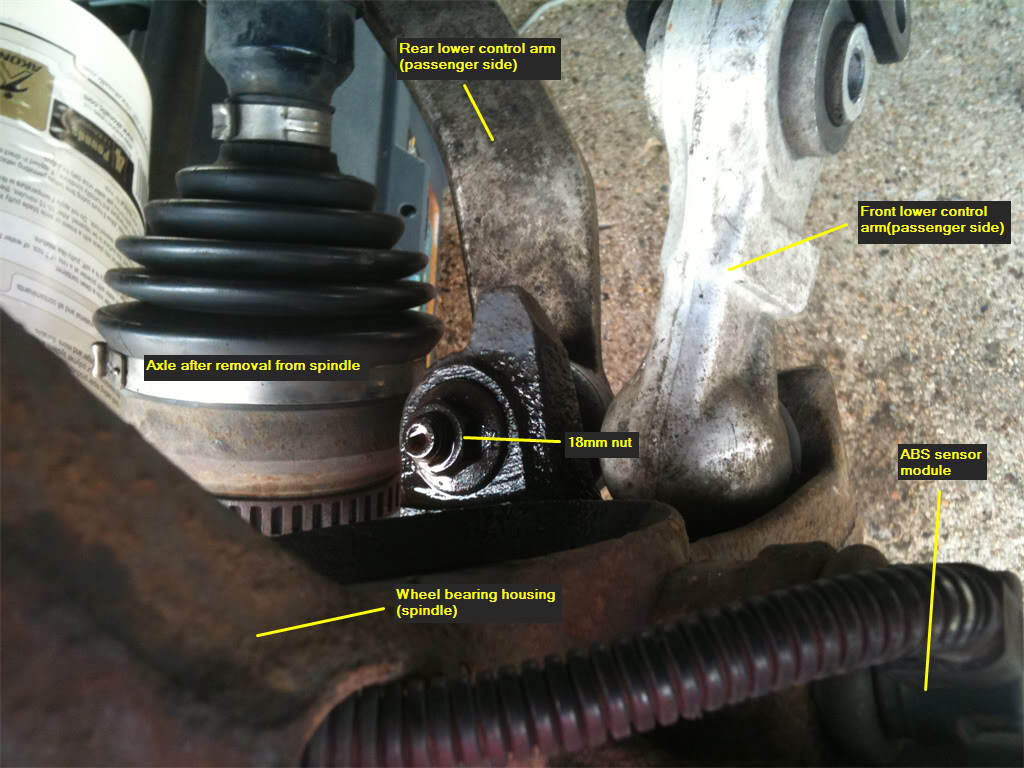
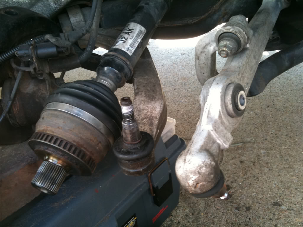
Step 28. Since the upper control arms and tie rod ends are out of the spindle now, it will be fairly easy to move the spindle around. You might be able to wiggle the axle out of the spindle by also pulling the spindle forward at the same time. If this works, this is what the axle will look like after it's out of the spindle. Once out of the spindle, you can swing the axle to either side in order to work on the lower control arms.
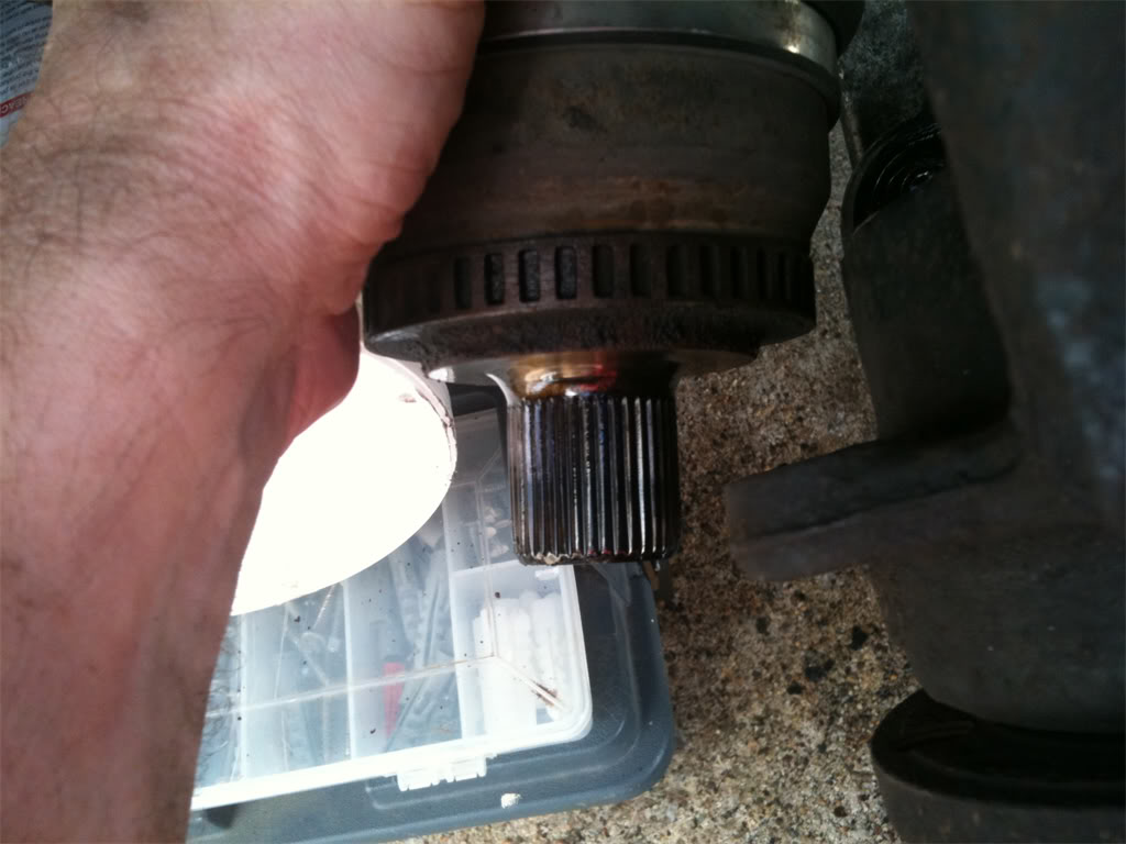
If you weren't able to get the axle out using that method, then just go ahead and proceed with removing the lower control arms and sway bar links. You'll be able to get the axle out without difficulties with those disconnected.
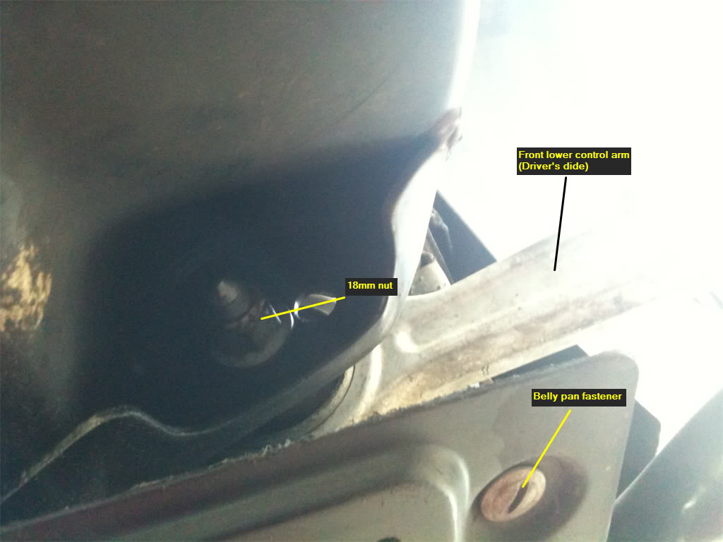
Step 29. Remove the belly pan that protects the oil pan and front part of the car from rocks and debris on the road. The belly pan is held on by approximately 10 fasteners and screws. Here's a view of the underside of the car that includes the lower front control arm and a belly pan fastener.
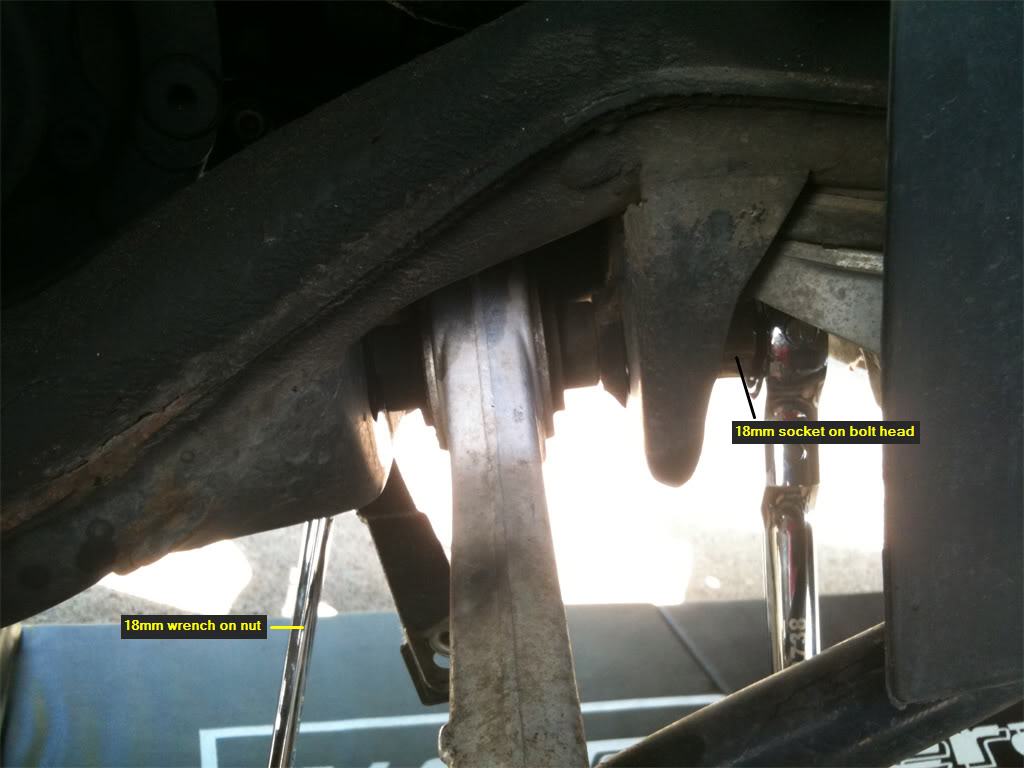
Step 30. Loosen the lower front and rear control arm bolts that are attached to the sub frame first. This is very straight-forward, and shouldn't be a problem. Both control arms use 18mm bolts.
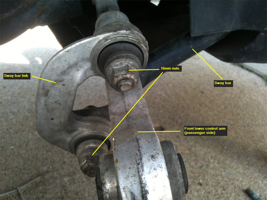
Step 31. Next, remove the sway bar links that attach to the lower front control arm and the sway bar. The bolts and nuts are 16mm.
Step 32. Now, you're going to remove the 18mm nuts from both the front and rear lower control arms. As this picture shows, the nut for the rear control arm is on the top of the spindle.
And this pic shows that the nut for the front control arm is on the bottom of the spindle.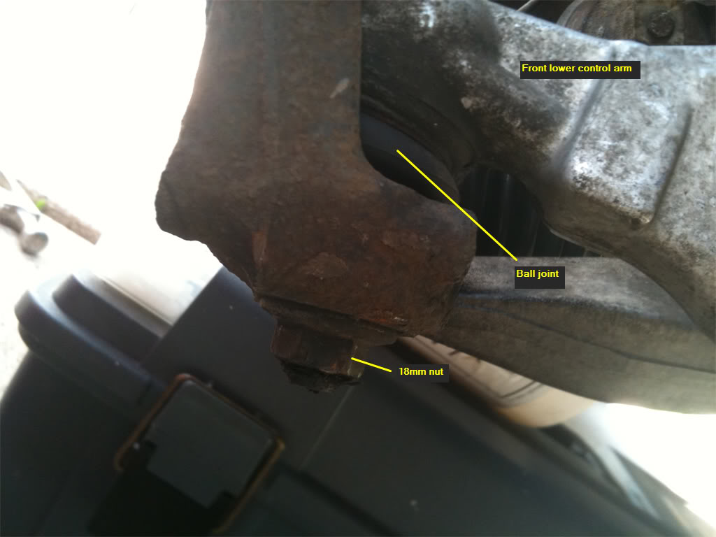
Those of you who removed the axle from the spindle will benefit from having clear access to the rear control arm bolt, and may use a socket on this one. If you left the spindle alone, you will probably have to use an 18mm wrench to remove the nut.
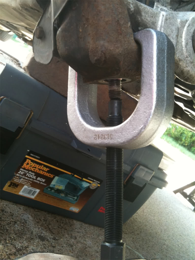
Step 33. With the nut removed, you can now pop the ball joints of both control arms out of the spindle. To accomplish this, I used one of those handy tools from the front end service kit that I purchased for this job. By using this tool, I had both ball joints out of the spindle in 5 minutes. When the ball joints pop out, there will be a loud SNAP! Don't worry, you didn't break anything.
With the ball joints out of the spindle, you may either set the spindle to the side, like I did, or remove it completely out of the picture by removing the ABS brake sensor. I've heard that the ABS sensor just pulls out of the spindle, and then you can pull it through the spindle. The spindle can be removed completely now.
In my case, my ABS sensors looked really rusty, and didn't pull off easily when I tugged on them. So, I ended up deciding not to press my luck and take the chance that I would break them. I just left the ABS sensor alone and carefully laid the spindle down off to the side, supported by a tool box.
Step 34. Ok, go ahead and finish removing the bolts from the lower front control arms. They will be easy to remove. The bolts are long, but can be threaded through the chassis and removed without any problems.
Step 35. I wish the same could be said of the bolts on the lower rear control arms. Getting these out will require a few extra steps, and the passenger side is a bonafide PITA to get out. Let's hope that the Audi engineer who thought up this design is now asking people "Would you like fries with that" at work instead of designing automobiles.
I'll concentrate on the passenger side, because once you can do this side, the driver's side will seem like child's play. First, a look at the problem and the obstacles.
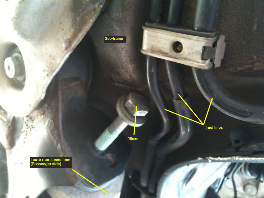
As you can see, you can't unscrew the bolt out far enough to get it out without hitting the subframe and the three fuel lines. To solve this problem, the first thing you'll do is loosen the 18mm bolt holding the subframe shield to the subframe. Loosen it about one inch.
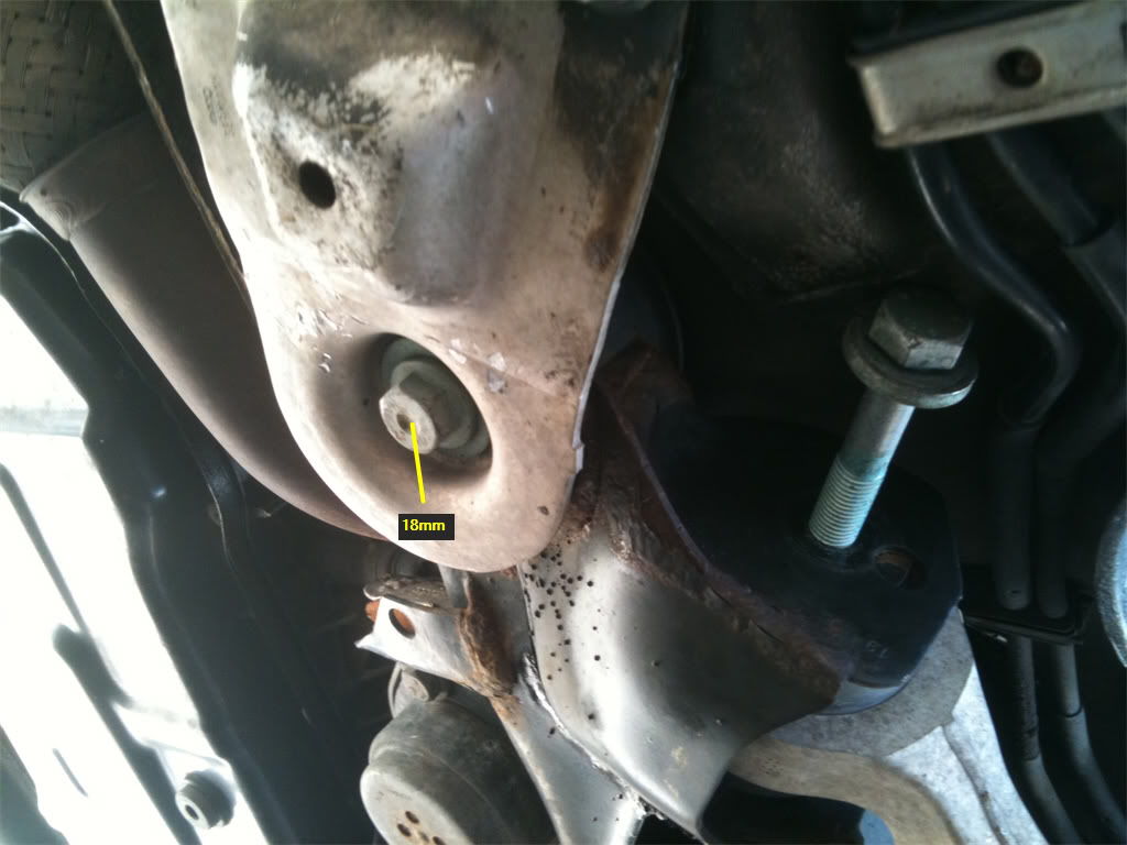
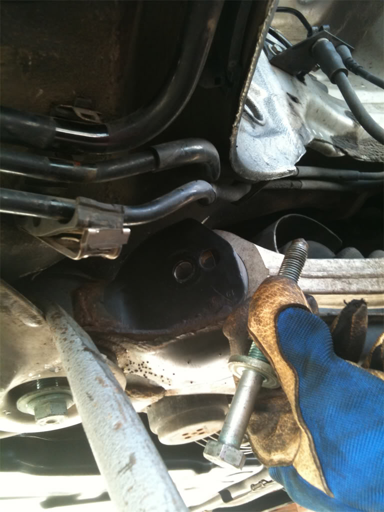
Next, pry the clip down that secures the three fuel lines. This will allow the clip to pop open. I used a flat head screwdriver to accomplish this. Once free, move the fuel lines out of the way. Using a pry bar, pull the subframe down while at the same time wiggling the bolt past the subframe and between the fuel lines. This part takes a little bit of experimenting with, but you'll eventually get it.
And here is the freed bolt, courtesy of some stupid engineering, and your strenuous efforts.
Step 36. Whew, now you can go ahead and remove the driver's side lower rear control arm. Same method, but no fuel lines to worry about. This will be much easier than the passenger side.
Congrats! You are almost done. All you have to do is install the new control arms and tie rod ends, if you were one who chose to remove the spindle. If you left the spindle alone, you probably already installed the new tie rod ends and the upper control arms.
Another word of caution. Since putting together the suspension is sort of like a jigsaw puzzle, it's best to leave all the bolts and nuts loose until you get everything together.
Before tightening the bolts and nuts down tight, using the torque specs below, it is critical that you apply load to the suspension first. If you tighten the control arms and tie rod ends without having load on the suspension, you will wear these parts out prematurely, and will have to do this job all over again soon!
To put the suspension under load, simply place your jack under the lower rear control arm's ball joint, and jack up the spindle until it's at a level with where it normally sits when the car is on it's wheels on the ground. You don't have to be perfect with this step, just eyeball it.
Here are the torque specs for the control arms:
Upper front - 50 Nm + 1/4 turn into mounting bracket
Upper rear - 50Nm + 1/4 turn into mounting bracket
Upper pinch bolt - 40 Nm
Lower front - 80 Nm + 1/4 turn into subframe
Lower rear - 90 Nm +1/4 turn into subframe
Lower control arms into the spindle - 100 Nm
Shock tower assembly bolts - 75 Nm
Lower nut and bolt into control arm - 90 Nm
Lower connection to the sway bar - 45 Nm
Upper connection into the control arm - 40 Nm + 1/4 turn
Rear Sub Frame, Large Bolt 110 Nm + 1/4 turn
Axle bolt - 200 Nm(My torque wrench doesn't go this high, so I just put my breaker bar with the pipe on it, and torqued it for all I was worth).
When you are all done with the job, make sure you take your car to the dealer or an alignment shop and get a four-wheel alignment. If you decide to be cheap and ignore this vital step, you could be looking at having to purchase new tires sooner than you would have to with a well-aligned car.
And now, my friends, it's time for the final and most satisfying step. As you are standing back and admiring your work, go to the fridge and get yourself a few of these, as a reward for a job well done. You've earned it!

We're in the home stretch, so let's do it!
Way back in part 1, I gave you the option of leaving the wheel bearing housing(aka "the spindle") alone, or removing it. If you decided that you wanted to remove it to replace the front wheel bearings, or if you just want more room to maneuver while changing everything else out, continue to step 27. Those of you who decided to leave the spindle alone can skip ahead to step 29.
Step 27. To remove the axle from the spindle, turn the axle bolt counter clockwise a few turns, then push it in with both thumbs while holding onto the spindle with the rest of your fingers. Using this method, continue to work the axle out of the housing until you can no longer move the axle with the axle bolt. You may then remove the axle bolt and place it somewhere where it won't get dirty or contaminated with anything.
Looking into the hole where the axle bolt was, this is what we see:
Step 28. Since the upper control arms and tie rod ends are out of the spindle now, it will be fairly easy to move the spindle around. You might be able to wiggle the axle out of the spindle by also pulling the spindle forward at the same time. If this works, this is what the axle will look like after it's out of the spindle. Once out of the spindle, you can swing the axle to either side in order to work on the lower control arms.
If you weren't able to get the axle out using that method, then just go ahead and proceed with removing the lower control arms and sway bar links. You'll be able to get the axle out without difficulties with those disconnected.
Step 29. Remove the belly pan that protects the oil pan and front part of the car from rocks and debris on the road. The belly pan is held on by approximately 10 fasteners and screws. Here's a view of the underside of the car that includes the lower front control arm and a belly pan fastener.
Step 30. Loosen the lower front and rear control arm bolts that are attached to the sub frame first. This is very straight-forward, and shouldn't be a problem. Both control arms use 18mm bolts.
Step 31. Next, remove the sway bar links that attach to the lower front control arm and the sway bar. The bolts and nuts are 16mm.
Step 32. Now, you're going to remove the 18mm nuts from both the front and rear lower control arms. As this picture shows, the nut for the rear control arm is on the top of the spindle.
And this pic shows that the nut for the front control arm is on the bottom of the spindle.
Those of you who removed the axle from the spindle will benefit from having clear access to the rear control arm bolt, and may use a socket on this one. If you left the spindle alone, you will probably have to use an 18mm wrench to remove the nut.
Step 33. With the nut removed, you can now pop the ball joints of both control arms out of the spindle. To accomplish this, I used one of those handy tools from the front end service kit that I purchased for this job. By using this tool, I had both ball joints out of the spindle in 5 minutes. When the ball joints pop out, there will be a loud SNAP! Don't worry, you didn't break anything.
With the ball joints out of the spindle, you may either set the spindle to the side, like I did, or remove it completely out of the picture by removing the ABS brake sensor. I've heard that the ABS sensor just pulls out of the spindle, and then you can pull it through the spindle. The spindle can be removed completely now.
In my case, my ABS sensors looked really rusty, and didn't pull off easily when I tugged on them. So, I ended up deciding not to press my luck and take the chance that I would break them. I just left the ABS sensor alone and carefully laid the spindle down off to the side, supported by a tool box.
Step 34. Ok, go ahead and finish removing the bolts from the lower front control arms. They will be easy to remove. The bolts are long, but can be threaded through the chassis and removed without any problems.
Step 35. I wish the same could be said of the bolts on the lower rear control arms. Getting these out will require a few extra steps, and the passenger side is a bonafide PITA to get out. Let's hope that the Audi engineer who thought up this design is now asking people "Would you like fries with that" at work instead of designing automobiles.
I'll concentrate on the passenger side, because once you can do this side, the driver's side will seem like child's play. First, a look at the problem and the obstacles.
As you can see, you can't unscrew the bolt out far enough to get it out without hitting the subframe and the three fuel lines. To solve this problem, the first thing you'll do is loosen the 18mm bolt holding the subframe shield to the subframe. Loosen it about one inch.
Next, pry the clip down that secures the three fuel lines. This will allow the clip to pop open. I used a flat head screwdriver to accomplish this. Once free, move the fuel lines out of the way. Using a pry bar, pull the subframe down while at the same time wiggling the bolt past the subframe and between the fuel lines. This part takes a little bit of experimenting with, but you'll eventually get it.
And here is the freed bolt, courtesy of some stupid engineering, and your strenuous efforts.
Step 36. Whew, now you can go ahead and remove the driver's side lower rear control arm. Same method, but no fuel lines to worry about. This will be much easier than the passenger side.
Congrats! You are almost done. All you have to do is install the new control arms and tie rod ends, if you were one who chose to remove the spindle. If you left the spindle alone, you probably already installed the new tie rod ends and the upper control arms.
Another word of caution. Since putting together the suspension is sort of like a jigsaw puzzle, it's best to leave all the bolts and nuts loose until you get everything together.
Before tightening the bolts and nuts down tight, using the torque specs below, it is critical that you apply load to the suspension first. If you tighten the control arms and tie rod ends without having load on the suspension, you will wear these parts out prematurely, and will have to do this job all over again soon!
To put the suspension under load, simply place your jack under the lower rear control arm's ball joint, and jack up the spindle until it's at a level with where it normally sits when the car is on it's wheels on the ground. You don't have to be perfect with this step, just eyeball it.
Here are the torque specs for the control arms:
Upper front - 50 Nm + 1/4 turn into mounting bracket
Upper rear - 50Nm + 1/4 turn into mounting bracket
Upper pinch bolt - 40 Nm
Lower front - 80 Nm + 1/4 turn into subframe
Lower rear - 90 Nm +1/4 turn into subframe
Lower control arms into the spindle - 100 Nm
Shock tower assembly bolts - 75 Nm
Lower nut and bolt into control arm - 90 Nm
Lower connection to the sway bar - 45 Nm
Upper connection into the control arm - 40 Nm + 1/4 turn
Rear Sub Frame, Large Bolt 110 Nm + 1/4 turn
Axle bolt - 200 Nm(My torque wrench doesn't go this high, so I just put my breaker bar with the pipe on it, and torqued it for all I was worth).
When you are all done with the job, make sure you take your car to the dealer or an alignment shop and get a four-wheel alignment. If you decide to be cheap and ignore this vital step, you could be looking at having to purchase new tires sooner than you would have to with a well-aligned car.
And now, my friends, it's time for the final and most satisfying step. As you are standing back and admiring your work, go to the fridge and get yourself a few of these, as a reward for a job well done. You've earned it!
Last edited by jonbonesjones; 02-21-2013 at 11:08 AM.
#2
08-25-2011, 07:05 PM
Awesome series man, about as thorough as I've ever seen. Glad you picked good beer too. Might I suggest adding Paulaner, Wiehenstephaner, or Hobgoblin to your supply?
The only thing I'd add is that for the end axle bolt, due to the extreme torque, it may be advisable to replace it if you loosen it. And to hit the target torque for it, give it 140 ft-lbs on the torque wrench, and then a 180 degree further turn with the breaker bar.
Kickass man - anyone contemplating the job will easily be able to see whether it's within their capabilities. Standing ovation from me and many others I'm sure.
#4
08-25-2011, 08:33 PM
Chris, I'm going to move them all to the DIY forum. Details in my post on the Part I installment.


Thread
Thread Starter
Forum
Replies
Last Post
jdahlen24
DIY - Do It Yourself
7
08-25-2011 09:51 PM
jdahlen24
DIY - Do It Yourself
0
08-25-2011 03:05 PM
jdahlen24
DIY - Do It Yourself
0
08-25-2011 12:49 PM