
W/M install complete. (Stage 2 MAF Kit) *** All is not Lost ***


5th Gear
Joined: Sep 2005
Posts: 6,678
From: Colchester, VT
Well... I've already seen pics of the install, unless he's got pics of his car doing wheelies, its time to move on to my other love, dogs with things on their heads. ; )
Thread Starter
|
2nd Gear
Joined: Oct 2006
Posts: 1,362
From: Columbus, GA
First off... lmfao @ ^^ that.
Ok, well during the first few runs after the install... I felt a definite increase in power; quite a bit actually. I'd say about 5-10hp at least. (without any timing or boost adjustments)
Its 4am now, so I'll post pictures with brief descriptions... but the notes and install instructions and tips will come when i wake up
ok here ya go:
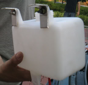
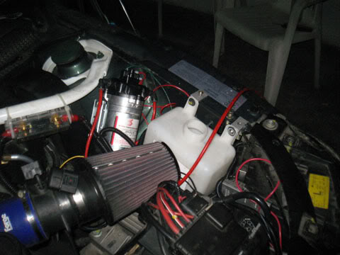
Took a piece of aluminum "L" stock and cut two 1" wide brackets to mount the tank. to the inside fender wall.
Here's the tank mounted on the fenderwall with the L brackets.
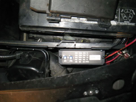
Hard to see, but that is the controller, mounted on the front side of the Battery housing between the housing and the firewall; harness facing down, controls facing up. DUR!
Okay, the yellow wire going into the blue piggyback splice is coming from the w/m controller and tapping into the MAF 0-5v output wire (black MAF wire). This was actually very much a PITA. The black MAF wire was soooo otiny... that the piggyback wouldn't break through the insulation on it and make a connection. That mixed with the fact that the yellow wire from the controller was NOT skinny at all... in fact it was fat... made it hard to do the splice and we had to keep redoing it and checking the yellow wire for voltage with the multimeter until it was good.
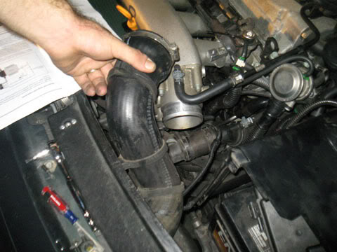
Removing the Charge pipe from the throttle body was a PITA since we'd had the car running alot to get the pump and settings right.

Drilling a hole in the charge pipe about half the diameter of the nozzle so that it fits VERY TIGHT, and threads in to the pipe actually. (note: I ordered the rubber hose adapter today because the kit only comes with connections for a metal charge pipe and I'll be changing it later once the adapter comes in.)
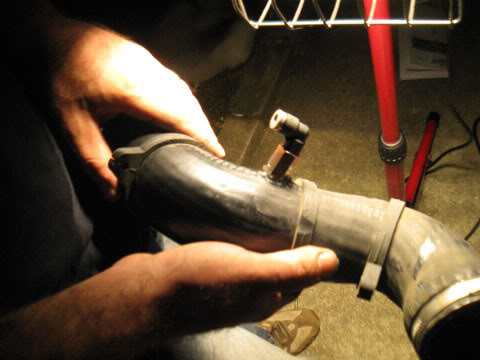
Once the nozzle was in a little bit, we coated the threads with GOOP and screwed it in the rest of the way. This picture doesn't show it but I also piled on plenty of silicone around the GOOP once the GOOP was dry to add more sealing. (didnt leak at all on the first 5 runs btw)

Rocco here decided he wanted some chips. Once his head was in, we pulled it the rest of the way on. lol
He ran around looking up and down and stuff trying to figure out where he was. kinda funny, but we took it off a few minutes later.
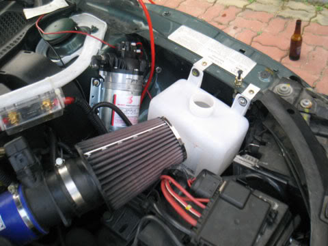
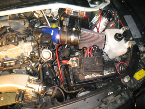
Everything mounted. This was when we were doing injection controller operational checks and tuning it to the right pressure and onset. Hence the tube hanging over the fender. btw... it took us a few minutes to understand why giving it gas wouldn't cut on the spray... until we noticed (seen in this picture) that the MAF was unplugged still.
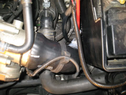
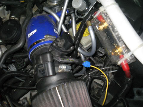
not a very good picture, but thats the chargepipe reinstalled with the nozzle in it.
Mission complete with cowlings off.

Mission complete with cowlings on.
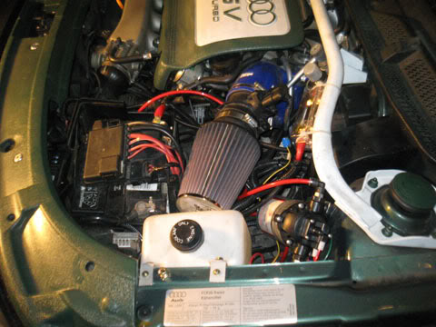
Side view with cowlings on.
Well, I'll edit this later and add some more install notes. Im kind of tired and need to do some software tweaks tomorrow. Good night, hope this helps.
Ok, well during the first few runs after the install... I felt a definite increase in power; quite a bit actually. I'd say about 5-10hp at least. (without any timing or boost adjustments)
Its 4am now, so I'll post pictures with brief descriptions... but the notes and install instructions and tips will come when i wake up
ok here ya go:
Took a piece of aluminum "L" stock and cut two 1" wide brackets to mount the tank. to the inside fender wall.
Here's the tank mounted on the fenderwall with the L brackets.
Hard to see, but that is the controller, mounted on the front side of the Battery housing between the housing and the firewall; harness facing down, controls facing up. DUR!
Okay, the yellow wire going into the blue piggyback splice is coming from the w/m controller and tapping into the MAF 0-5v output wire (black MAF wire). This was actually very much a PITA. The black MAF wire was soooo otiny... that the piggyback wouldn't break through the insulation on it and make a connection. That mixed with the fact that the yellow wire from the controller was NOT skinny at all... in fact it was fat... made it hard to do the splice and we had to keep redoing it and checking the yellow wire for voltage with the multimeter until it was good.
Removing the Charge pipe from the throttle body was a PITA since we'd had the car running alot to get the pump and settings right.
Drilling a hole in the charge pipe about half the diameter of the nozzle so that it fits VERY TIGHT, and threads in to the pipe actually. (note: I ordered the rubber hose adapter today because the kit only comes with connections for a metal charge pipe and I'll be changing it later once the adapter comes in.)
Once the nozzle was in a little bit, we coated the threads with GOOP and screwed it in the rest of the way. This picture doesn't show it but I also piled on plenty of silicone around the GOOP once the GOOP was dry to add more sealing. (didnt leak at all on the first 5 runs btw)
Rocco here decided he wanted some chips. Once his head was in, we pulled it the rest of the way on. lol
He ran around looking up and down and stuff trying to figure out where he was. kinda funny, but we took it off a few minutes later.
Everything mounted. This was when we were doing injection controller operational checks and tuning it to the right pressure and onset. Hence the tube hanging over the fender. btw... it took us a few minutes to understand why giving it gas wouldn't cut on the spray... until we noticed (seen in this picture) that the MAF was unplugged still.
not a very good picture, but thats the chargepipe reinstalled with the nozzle in it.
Mission complete with cowlings off.
Mission complete with cowlings on.
Side view with cowlings on.
Well, I'll edit this later and add some more install notes. Im kind of tired and need to do some software tweaks tomorrow. Good night, hope this helps.

1st Gear
Joined: Feb 2006
Posts: 437
ORIGINAL: achTTung
Well... I've already seen pics of the install, unless he's got pics of his car doing wheelies, its time to move on to my other love, dogs with things on their heads. ; )
Well... I've already seen pics of the install, unless he's got pics of his car doing wheelies, its time to move on to my other love, dogs with things on their heads. ; )
5th Gear
Joined: Sep 2005
Posts: 6,678
From: Colchester, VT
That was an awesome pic.
The whole install looks involved, good work with the documentation. Anytime I get under the hood, once I start getting grease on my hands, I forget I have the camera there.
The whole install looks involved, good work with the documentation. Anytime I get under the hood, once I start getting grease on my hands, I forget I have the camera there.
Thread Starter
|
2nd Gear
Joined: Oct 2006
Posts: 1,362
From: Columbus, GA
Nate, with the gt3076 turbo package from Pagparts... what size injectors would they give me for that and what type of tuning? Do they just send another ECU altogether? Is it standalone? and will they ask what Im looking for out of it or will it be a prefab product? Reason being... I'd like some type of w/m sensing software embedded in it.
You can get a low level indicator LED upgrade (uses a bobbing device to read fluid level and sends low voltage signal to an LED when low or out. I'd like someway to integrate that into the ECU to retard timing once I run dry on w/m. How possible you think this is? Would it be as easy as them embedding it and installing a wire terminal on the ECU for the low level indicator signal wire to attach to?
Ok... now im going to sleep. I don't know why I think you'll know the answer to any of that... but for some reason I bet you do. lol
**EDIT**
By the way... this whole process would be a helluva lot easier after a battery relocation. I think once I get my Audio stuff going and finish the false floor in the back... Im gonna make a compartment in the rear for the battery and run the wires down under the side skirts to the rear fenderwell. That battery area is SOOO full of battery that you could easily fit two or three of these installs there if the battery was gone.
I may actually put a 7qt tank or an aftercooler where the battery was after I relocate it.
Thread Starter
|
2nd Gear
Joined: Oct 2006
Posts: 1,362
From: Columbus, GA
ORIGINAL: achTTung
The whole install looks involved, good work with the documentation. Anytime I get under the hood, once I start getting grease on my hands, I forget I have the camera there.
The whole install looks involved, good work with the documentation. Anytime I get under the hood, once I start getting grease on my hands, I forget I have the camera there.
Plus, we had to figure a lot of it out ourselves since there isn't a writeup and the instructions kinda suck.