
2001 A4 Avant Sound System Build Thread

After a couple years of dealing with half of a factory sound system in my 2001 A4 Avant QTM, I'm finally making some changes. The trunk-mounted subwoofer/amplifier blew not long after I bought the car, so I've had only the front door-mounted speakers and tweeters functioning these last 2 years. Bleh, it sounds like crap.
So here is my sound system build thread. I've spent a lot of time considering my options these last couple years, and it's all finally culminating in this "grand plan". The components I'll be using:
- Nexus 7 2013 tablet for a head unit
- USB DAC for audio output
- AudioControl Epicenter Bass Processor
- AudioControl Three.2 in-dash EQ
- AudioControl EQS trunk-mounted equalizer
- AudioControl 6XS trunk-mounted electronic crossover
- Cadence Sound "Chicago" amplifier for front speakers and tweeters
- Cadence Sound "Vegas" amplifier for rear speakers and subwoofer
- CDT ES-04 4" mid woofers for the front doors
- CDT HD-1 1" tweeters for the front doors
- CDT WS-100i 1" imaging tweeters for the windshield
- CDT ES-6im 6.5" woofers for the rear doors
- CDT HD-1000 10" subwoofer for the trunk
Questions you're probably asking:
Don't you realize there are more modern audio processing components than that outdated AudioControl stuff? How about a JL Audio MS-8 or an Arc PS-8 or a Rockford Fosgate 3sixty.3?
- I want to maintain an all-analog signal path from the DAC onwards. The DAC I'm using outputs a 24bit/96khz resolution signal, so I'd like to keep it that way all the way to the speakers. I have a large collection of FLAC music files that were mastered in 96khz. ALL current digital processors downsample that to 48khz. Also, most digital processors have an annoying limit on input signal voltage, which I find restrictive. As a bonus, I already had some of this stuff laying around from a setup in a previous vehicle, so that saves me money.
But Frank! Why only use 4" drivers in the front doors when most people stuff 5.25" drivers?
- because I love the sound of the CDT ES-04 speakers, and the rear door speakers (with 6.5" drivers) are immediately behind me anyways. Also, 4" drivers fit better in the doors with minimal modifications. These speakers can go all the way down to 100hz without breaking a sweat, although I only plan to run them down to 250hz.
Wow, that system should look killer!
- I hope not... I'm planning to hide everything so it appears bone stock to anyone who looks in through the window, with the exception of the touch screen where the head unit should be. I also want to make it as reversible as possible, so I can take the stuff out and keep it if I decide to sell this car.
And so begins the build thread! My first order of business will be to run the power cable from the battery to the trunk. Stay tuned!
(note: I'm mostly a stay-at-home dad these days, so the only time I get to work on this project is during my daughter's 2x2 hour naps from 10-12 and 3-5)
Last edited by GoremanX; Jun 1, 2014 at 05:09 PM.
First order of business, the power cable! I need to run a 0 gauge cable from the battery to the trunk, then split it into 4 gauge cables for the pair of amplifiers. For this, I bought a dual amp power kit from KnuKonceptz. The main power cable in this kit is an 18 foot long true 0 gauge oxygen-free copper (not copper-clad aluminum). There's also a battery terminal block, an inline fuse, a distribution block with 2 more fuses, 6 feet of 4 gauge power cable, 8 feet of 4 gauge ground cable, and 2 feet of 0 gauge ground cable, along with some odds and ends like terminal rings and other miscellaneous stuff.
The one thing missing from this kit is a ground distribution block... this seems like a very odd omission. And while the battery terminal block and power distribution block use excellent compression fittings for connections, the inline fuse holder has standard hex set-screws... another odd choice. So in addition to the kit, I also bought a second power distribution block (with copper links rather than fuses) so I can have a single ground point, and a different inline fuse holder that has compression fittings.
This is the best power cable I've ever worked with. It's HUGE, bigger than most 0/1 gauge cable I've seen. It has over 5000 strands, and is unbelievably flexible.
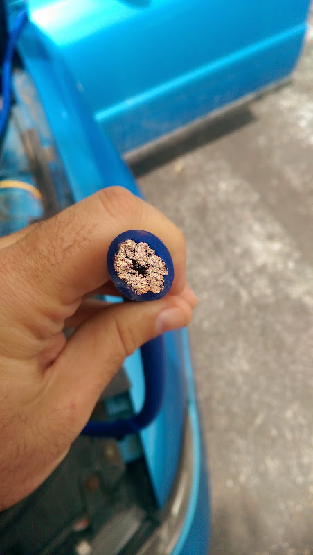
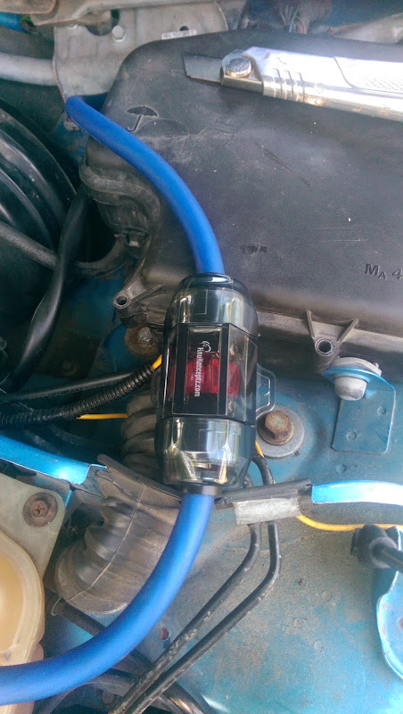
And it just happens to be blue, much like my car This is the standard cable color in the kit, so it's just a coincidence. KnuKonceptz carries a "Kandy" blue as well, which matches my car's color even better, but this one looks fine to me:

I have a very standard battery in there, but I may replace it with something a little more high-end in the future. So I'm leaving myself enough cable to be able to reach either of the battery posts (most high end batteries aren't available with the positive terminal on the left side):
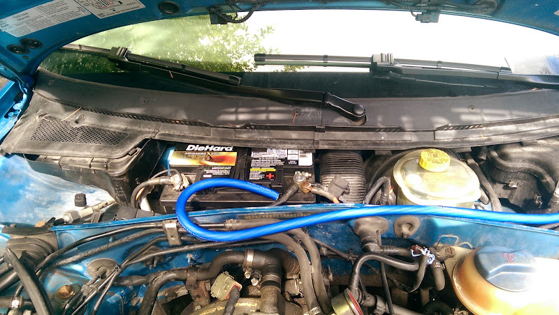
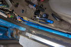
I tried running the cable along the side of the car first to see if it would be long enough. It seems like a really close fit, I sure hope it reaches!
There's going to be a potential 150 amps running through this cable, so I'm trying to run it as far from vital components (like the ECU) as possible. That plastic collar at the ECU box will be replaced with a rubber grommet soon:

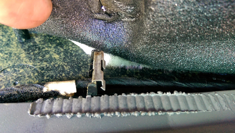
Note that I had to remove the windshield wipers and unbolt the wiper transmission to gain better access to the ECU box from the back like this. It keeps the cable better hidden from sight, and away from sensitive electronic components.
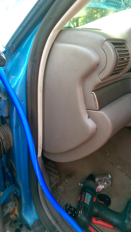
Wow, that interior is filthy! I'll have to give it a good vacuuming soon. At this point I've got the under-dash knee bolster removed and the cable dropping down from the ECU box:
(yes, my door hinges are in pretty bad shape too)
Removing the kick panel and dead pedal reveals... not a whole lot of room. It's a damn tight fit in there for such a huge cable. I'm always shocked whenever I see all the crap Audi crammed behind that kick panel.

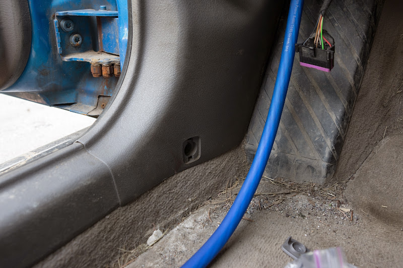
Running the cable under the carpet is a really tight fit. I have to forge my own path, because following the existing wiring harness leaves me with too big a bulge. I'm running the cable along the top of the seat track, which gives it a nice groove to sit in and should prevent movement.

(when I run the audio cables on the other side of the car, I'll document how I removed the trim to gain access to all this)
Here we are beside the rear seat. Look at the size of that factory harness!!! It's no wonder Audis are plagued with electrical gremlins with age.

Here I can use the factory fasteners to hold the cable in place, it's very convenient. This is running up the C pillar beside the rear seat:
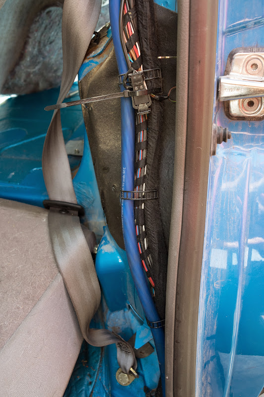
And into this convenient hole, seemingly made for my cable. How thoughtful!

While the following picture shows the cable running along the top of the wheel well, I actually changed it so it came out of that large hole just below the seat belt tensioner and ran along the floor next to the wheel well. That gave me a few extra precious inches...

...to arrive EXACTLY where I needed to! Phew, not an inch to spare:

BEHOLD the remnants of baking soda littering my trunk floor, from a gas spill incident 2 years ago and subsequent attempts to clean out the gas smell. Baking soda worked well, but it is messy. I gotta clean all that stuff up!
So the 18 foot cable ended up being absolutely perfect for my needs. I spent an hour putting all the trim back together, and there's no hint of any new cable in sight.
The cable is NOT yet hooked up to the battery. I'll get to that when it's time to power the amps. In a couple days I plan to install the new inline fuse holder, so I'll show more details of how the cable is routed around the battery.
Tomorrow, I'll be routing the RCA cables along the right side of the car!
The one thing missing from this kit is a ground distribution block... this seems like a very odd omission. And while the battery terminal block and power distribution block use excellent compression fittings for connections, the inline fuse holder has standard hex set-screws... another odd choice. So in addition to the kit, I also bought a second power distribution block (with copper links rather than fuses) so I can have a single ground point, and a different inline fuse holder that has compression fittings.
This is the best power cable I've ever worked with. It's HUGE, bigger than most 0/1 gauge cable I've seen. It has over 5000 strands, and is unbelievably flexible.
And it just happens to be blue, much like my car
This is the standard cable color in the kit, so it's just a coincidence. KnuKonceptz carries a "Kandy" blue as well, which matches my car's color even better, but this one looks fine to me:I have a very standard battery in there, but I may replace it with something a little more high-end in the future. So I'm leaving myself enough cable to be able to reach either of the battery posts (most high end batteries aren't available with the positive terminal on the left side):
I tried running the cable along the side of the car first to see if it would be long enough. It seems like a really close fit, I sure hope it reaches!
There's going to be a potential 150 amps running through this cable, so I'm trying to run it as far from vital components (like the ECU) as possible. That plastic collar at the ECU box will be replaced with a rubber grommet soon:
Note that I had to remove the windshield wipers and unbolt the wiper transmission to gain better access to the ECU box from the back like this. It keeps the cable better hidden from sight, and away from sensitive electronic components.
Wow, that interior is filthy! I'll have to give it a good vacuuming soon. At this point I've got the under-dash knee bolster removed and the cable dropping down from the ECU box:
(yes, my door hinges are in pretty bad shape too)
Removing the kick panel and dead pedal reveals... not a whole lot of room. It's a damn tight fit in there for such a huge cable. I'm always shocked whenever I see all the crap Audi crammed behind that kick panel.
Running the cable under the carpet is a really tight fit. I have to forge my own path, because following the existing wiring harness leaves me with too big a bulge. I'm running the cable along the top of the seat track, which gives it a nice groove to sit in and should prevent movement.
(when I run the audio cables on the other side of the car, I'll document how I removed the trim to gain access to all this)
Here we are beside the rear seat. Look at the size of that factory harness!!! It's no wonder Audis are plagued with electrical gremlins with age.
Here I can use the factory fasteners to hold the cable in place, it's very convenient. This is running up the C pillar beside the rear seat:
And into this convenient hole, seemingly made for my cable. How thoughtful!
While the following picture shows the cable running along the top of the wheel well, I actually changed it so it came out of that large hole just below the seat belt tensioner and ran along the floor next to the wheel well. That gave me a few extra precious inches...
...to arrive EXACTLY where I needed to! Phew, not an inch to spare:
BEHOLD the remnants of baking soda littering my trunk floor, from a gas spill incident 2 years ago and subsequent attempts to clean out the gas smell. Baking soda worked well, but it is messy. I gotta clean all that stuff up!
So the 18 foot cable ended up being absolutely perfect for my needs. I spent an hour putting all the trim back together, and there's no hint of any new cable in sight.
The cable is NOT yet hooked up to the battery. I'll get to that when it's time to power the amps. In a couple days I plan to install the new inline fuse holder, so I'll show more details of how the cable is routed around the battery.
Tomorrow, I'll be routing the RCA cables along the right side of the car!
Last edited by GoremanX; Jun 1, 2014 at 05:39 PM.
There's been a little delay in the RCA cable installation. I purchased some "premium" RCA cables from Monoprice, but they ended up being anything but "premium". They're a nightmare to work with, and 2 of them won't even connect to any jacks because the ground shield is too tight. Attempting to open up the ground shield has caused a jaw to break right off. This stuff is really abysmal. After all the positive reviews I read about these cables all over the intertubes, I'm really disappointed. These things are nothing more than budget Chinese crap with a thicker, stiffer sheath.
Awaiting new RCA cables...
I do have an update regarding the power cable accessorie though. I'll get to that in a couple hours.
Awaiting new RCA cables...
I do have an update regarding the power cable accessorie though. I'll get to that in a couple hours.
I received the new inline fuse holder and distribution block from KnuKonceptz today, I'm much happier with this fuse holder than I was with the one that was included with the kit. Not sure why they don't include it in the first place.
On the left is the fuse holder that was included in the kit, with set screws to hold the cable in place. On the right is the different one I ordered, with compression fittings instead:
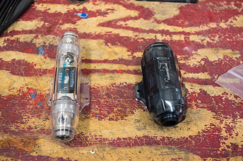
The way they work is very different too. The old one uses a single ANL fuse (150 amps in my case). The new one uses 3 mini ANL fuses in parallel (3 x 50 amps).

Supposedly, this results in less voltage drop thanks to the increased surface area and reduced resistance of 3 fuses vs one. Personally, I find that it just triples the number of screws I need to loosen/tighten when installing the fuses. I will not be doing a voltage drop comparison test.
This is my real reason for wanting to use this different fuse holder. The compression fittings do a much better job of securing the cable in place while maximizing direct contact with as many strands as possible.

In case you've never used compression fittings, here's how they work. First you cut off about 3/4" of insulation from the cable:

Before proceeding any further, make SURE you put one of the fuse holder end caps over the wire, especially if the wire is already secured or inaccessible from the other end. Otherwise you'll hate life... guess how I know? Notice there's no end cap pictured from here on...
Once the end cap is on there (and in this case, a rubber gasket too), you stuff the conductor through the compression fitting. It's a REALLY tight fit *if* the strands are still tightly packed. If they're not, then it's a nearly impossible fit.
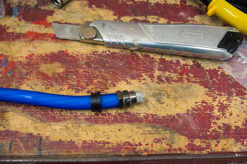
The insulation sits in there by about 1/4" too, but only the conductor can fit through the end of the fitting. Then you pull the strands down around the fitting...

...and you jam the whole thing into the fuse holder and tighten the fitting with a wrench. I forgot to take a picture of that, so here's a picture of the distribution block with the ground wire installed instead (and copper links rather than fuses):

Notice how there's no bare strands showing, just insulation coming right out of the fitting. It's a very clean and strong setup, holds extremely tight from around the entire cable and does a decent job of sealing against crap getting in there. Here's the fuse holder all assembled:

Another nice thing about this fuse holder is there's a thick rubber pad that goes under the mount, so there's less chance of it cracking when you bolt it down, or vibrating loose over time.
I really hope the fuses never blow, because I dread the prospect of having to replace them. It's a simple matter of unscrewing the end caps and pulling the holder out (with cable still attached), but changing 3 of those fuses seems like a pain.
Hopefully tomorrow I can put the fuse holder into the car and hook it up to the cable I already installed there.
On the left is the fuse holder that was included in the kit, with set screws to hold the cable in place. On the right is the different one I ordered, with compression fittings instead:
The way they work is very different too. The old one uses a single ANL fuse (150 amps in my case). The new one uses 3 mini ANL fuses in parallel (3 x 50 amps).
Supposedly, this results in less voltage drop thanks to the increased surface area and reduced resistance of 3 fuses vs one. Personally, I find that it just triples the number of screws I need to loosen/tighten when installing the fuses. I will not be doing a voltage drop comparison test.
This is my real reason for wanting to use this different fuse holder. The compression fittings do a much better job of securing the cable in place while maximizing direct contact with as many strands as possible.
In case you've never used compression fittings, here's how they work. First you cut off about 3/4" of insulation from the cable:
Before proceeding any further, make SURE you put one of the fuse holder end caps over the wire, especially if the wire is already secured or inaccessible from the other end. Otherwise you'll hate life... guess how I know? Notice there's no end cap pictured from here on...
Once the end cap is on there (and in this case, a rubber gasket too), you stuff the conductor through the compression fitting. It's a REALLY tight fit *if* the strands are still tightly packed. If they're not, then it's a nearly impossible fit.
The insulation sits in there by about 1/4" too, but only the conductor can fit through the end of the fitting. Then you pull the strands down around the fitting...
...and you jam the whole thing into the fuse holder and tighten the fitting with a wrench. I forgot to take a picture of that, so here's a picture of the distribution block with the ground wire installed instead (and copper links rather than fuses):
Notice how there's no bare strands showing, just insulation coming right out of the fitting. It's a very clean and strong setup, holds extremely tight from around the entire cable and does a decent job of sealing against crap getting in there. Here's the fuse holder all assembled:
Another nice thing about this fuse holder is there's a thick rubber pad that goes under the mount, so there's less chance of it cracking when you bolt it down, or vibrating loose over time.
I really hope the fuses never blow, because I dread the prospect of having to replace them. It's a simple matter of unscrewing the end caps and pulling the holder out (with cable still attached), but changing 3 of those fuses seems like a pain.
Hopefully tomorrow I can put the fuse holder into the car and hook it up to the cable I already installed there.
Last edited by GoremanX; Jun 4, 2014 at 11:39 PM.
Got the fuse holder mostly in place! There's a lot less room in there than I assumed
First, I added the rubber grommet I was planning on. This is a lot more reassuring than a loose-fitting plastic collar:

This time I remembered the end cap and rubber gasket before placing the compression fitting on the end of the cable.

Here we go, inline fuse holder is hooked up to the power cable...

...and its casing is sealed up tight
For now, I placed it under the brake fluid reservoir. I'll screw it into the side of this compartment when I'm ready to do final hook up to the battery.

I'm still waiting on the new RCA cables. There's been another minor delay in the meantime; my AudioControl EQS is defective The rear channel mangles any signal I try to send through it. Luckily it's still under warranty, so I hope to have a fully functional trunk-mounted EQ within a week or so. In the meantime, there's plenty more stuff left to do
First, I added the rubber grommet I was planning on. This is a lot more reassuring than a loose-fitting plastic collar:
This time I remembered the end cap and rubber gasket before placing the compression fitting on the end of the cable.
Here we go, inline fuse holder is hooked up to the power cable...
...and its casing is sealed up tight
For now, I placed it under the brake fluid reservoir. I'll screw it into the side of this compartment when I'm ready to do final hook up to the battery.
I'm still waiting on the new RCA cables. There's been another minor delay in the meantime; my AudioControl EQS is defective
The rear channel mangles any signal I try to send through it. Luckily it's still under warranty, so I hope to have a fully functional trunk-mounted EQ within a week or so. In the meantime, there's plenty more stuff left to do
Since I was still waiting on RCA cables today, I decided to get started on sound deadening for the doors. I figure I'll do one door a day, as long as it's nice out. I started off with the driver's side door.
First thing I did is remove the interior door panel (what many people call the door card). This part is mostly easy and straightforward. There's a screw at the top of the door panel here:

and here:

Then on the inside pull handle, there's another screw holding a plastic trim in place. I removed the screw and pulled the plastic trim down until it was free (it's in there pretty tight). That reveals the last 2 screws holding the panel in place:

Once those screws are out, the panel comes off easily. I just used the inside pull handle to lift the entire panel up by about an inch, then away from the door. There's 7 plastic hooks on the panel that attach to the door, lifting it up by an inch moves those hooks out of their slots far enough to allow the panel to come off.
Once the panel is removed, I still had to disconnect countless wires and sockets. It's crazy how many wires go in there. Most of them are fairly straightforward, but the power window sockets ALWAYS give me trouble.

There's no release clip, I just have to pull on them hard enough until they come off. Half the time, one of the pins in the socket stays stuck on the switch and needs to be released separately. I've found that there's a release tab on every pin that allows it to release easily. The socket is "supposed" to press the release tabs on all the pins as you pull on it, but it works very poorly.
I also noticed that all the power window switch sockets are interchangeable. It's possible to plug any of them in the wrong place, so that the switches will work on the wrong doors. Luckily I took a picture before taking it apart.
Here's the removed door panel sitting on my "work bench" (trash and recycling bins side-by-side):

That foam insulation is pretty nice. I've worked on many cars before, and none of them had such a nice feature. It's usually just some cheap clear plastic with mastic to hold it in place. This foam pad mostly comes right off, there's just a strip of adhesive near the center holding it in place.
It's also sealed up against one of the electrical sockets, and it's pressed onto the tabs for the power window switches. It can easily come off without any damage. The seal around the socket is easy to pull off, but won't go back on afterwards, which isn't a big deal.
Here it is completely removed:

Note the white strip of adhesive in the middle. A lot of that wasn't even attached on mine.
And here's my bare door panel. As I mentioned earlier, I've done stuff like this on a few vehicles before, but this is the first one I work on with so many curves and compartments. This will be a bit more time-consuming than I expected.

This is the stuff I'll be using for sound deadener:

That's a 50 square foot roll of Fatmat Mega Mat. It's WAY cheaper than Dynamat, and I find that it's easier to work with too. I got 100 square feet for $240. That should be more than enough to deaden everything I plan to in the car. The bulk kit includes a small knife and a roller, which I find thoughtful. The roller works fine, and I've learned that using it gives longer-lasting results.
After lots of cutting and test fitting and applying and rolling and swearing... the vast majority of the door panel is covered in sound deadener:

(oh, and check out my finger in the shot... awesome)
I tried to avoid covering anything that might complicate future repairs, and I made sure not to add any deadener that would affect re-installing the panel. You can see a larger version of that picture here to get a better idea of where I did and didn't add deadener (it's a cell phone pic taken with my HTC One M8, don't expect miracles).
Now onto the door itself!
Wait, what? Seriously? I've covered the door panel in deadener, and now I'm going to do the door too? Yep, I'm real **** that way. Besides, I have 100 square feet of the stuff. Might as well use it! The stuff I got only weighs about 0.5 pound per square foot, which isn't the most dense on the market. But I picked that on purpose so I could choose to double-deaden where I want to without worrying about excess weight.
So here's the inside of the door with the panel removed:

Wow, that's a lot of stuff. Pardon the massive sun glare. This damn cell phone lens sucks. I'm impressed that Audi puts *some* sound deadener in there from the factory. That's more than most manufacturers bother to do. I've decided to keep it there and just cover it up with more deadener.
Notice the inside door handle is still attached. It's a lot easier to remove that entire piece from the panel than it is to unhook the door handle cable. It's held in place by just one screw, and then it clips right out of the door panel. There's also an electrical connector to unplug.
First I removed that white plastic shield. I don't know what it's for, but I figure it serves a purpose, so I'll be putting it back after. Therefore I'm being careful removing it:

Now there's that huge bizarre foam block. I can't even begin to guess what that thing does in life. It's hard and brittle, and it weighs next to nothing. If it's a way to dampen sound, it's serves that purpose poorly. In any case, it's there, so I'll put it back when I'm done. But dammit, it's riveted in place! So I drilled out the rivets and pulled it off:

I also removed a black plastic shield that goes over the latch mechanism. It was a tight fit, but it pulled right out without damage. Then I started cutting sheets of sound deadener. This is a test fit before I applied the sheet:

Word of advice: don't use such large sheets in such tight quarters, you'll be swearing a lot once you remove the backing and you try to slide in back in with the adhesive grabbing everything it touches. For the rest of the door, I used 3-4 smaller pieces rather than one long one:

I'm not going to bother adding deadener to the top section of the door (where there's a lone scrap piece in the picture). That part of the door is made of stiffer metal with reinforcements, and I think I've already gone way overkill with this door anyways.
Here's the door mostly re-assembled, with the plastic panels and foam block installed. At this time of day, I was having a hard time getting a proper picture with my phone (sun was way too bright), so I hauled out my DSLR just for this picture:

You can see the full size version here.
Notice I've got 2 zip ties holding the foam block in place. Remember I had to drill out the rivets that were holding it in place, and one of those holes is inaccessible for a bolt+nut (square tube). So I was able to get 2 bolts to hold it, but settled for zip ties for the other 2 supports.
That's about it! This door ended up taking me about 4 hours from start to final re-assembly (2 hours during my daughter's morning nap, and 2 hours during her afternoon nap), but I was figuring stuff out along the way. I think the passenger-side front door should only take me about 3 hours, and the rear doors might take 2 hours each since they're smaller. I have no clue how long the trunk hatch will take, or the cargo area.
But look what arrived while I was working on the sound deadener!

These are MUCH better than the Monoprice crap I got before. The short cables and the ends of the long ones are super-flexible, the plugs are small, and the long runs have a nice protective jacket. I'll be running two cables to the cargo area, one 4-channel and one 2-channel. I would've loved to get a 6-channel cable, but those are becoming rare as hen's teeth these days. I wasn't really impressed with Stinger's 4000 series cable, which is the only affordable 6-channel I could find in stock anywhere.
Anyways, another day done. Onto tomorrow!
First thing I did is remove the interior door panel (what many people call the door card). This part is mostly easy and straightforward. There's a screw at the top of the door panel here:
and here:
Then on the inside pull handle, there's another screw holding a plastic trim in place. I removed the screw and pulled the plastic trim down until it was free (it's in there pretty tight). That reveals the last 2 screws holding the panel in place:
Once those screws are out, the panel comes off easily. I just used the inside pull handle to lift the entire panel up by about an inch, then away from the door. There's 7 plastic hooks on the panel that attach to the door, lifting it up by an inch moves those hooks out of their slots far enough to allow the panel to come off.
Once the panel is removed, I still had to disconnect countless wires and sockets. It's crazy how many wires go in there. Most of them are fairly straightforward, but the power window sockets ALWAYS give me trouble.
There's no release clip, I just have to pull on them hard enough until they come off. Half the time, one of the pins in the socket stays stuck on the switch and needs to be released separately. I've found that there's a release tab on every pin that allows it to release easily. The socket is "supposed" to press the release tabs on all the pins as you pull on it, but it works very poorly.
I also noticed that all the power window switch sockets are interchangeable. It's possible to plug any of them in the wrong place, so that the switches will work on the wrong doors. Luckily I took a picture before taking it apart.
Here's the removed door panel sitting on my "work bench" (trash and recycling bins side-by-side):
That foam insulation is pretty nice. I've worked on many cars before, and none of them had such a nice feature. It's usually just some cheap clear plastic with mastic to hold it in place. This foam pad mostly comes right off, there's just a strip of adhesive near the center holding it in place.
It's also sealed up against one of the electrical sockets, and it's pressed onto the tabs for the power window switches. It can easily come off without any damage. The seal around the socket is easy to pull off, but won't go back on afterwards, which isn't a big deal.
Here it is completely removed:
Note the white strip of adhesive in the middle. A lot of that wasn't even attached on mine.
And here's my bare door panel. As I mentioned earlier, I've done stuff like this on a few vehicles before, but this is the first one I work on with so many curves and compartments. This will be a bit more time-consuming than I expected.
This is the stuff I'll be using for sound deadener:
That's a 50 square foot roll of Fatmat Mega Mat. It's WAY cheaper than Dynamat, and I find that it's easier to work with too. I got 100 square feet for $240. That should be more than enough to deaden everything I plan to in the car. The bulk kit includes a small knife and a roller, which I find thoughtful. The roller works fine, and I've learned that using it gives longer-lasting results.
After lots of cutting and test fitting and applying and rolling and swearing... the vast majority of the door panel is covered in sound deadener:
(oh, and check out my finger in the shot... awesome)
I tried to avoid covering anything that might complicate future repairs, and I made sure not to add any deadener that would affect re-installing the panel. You can see a larger version of that picture here to get a better idea of where I did and didn't add deadener (it's a cell phone pic taken with my HTC One M8, don't expect miracles).
Now onto the door itself!
Wait, what? Seriously? I've covered the door panel in deadener, and now I'm going to do the door too? Yep, I'm real **** that way. Besides, I have 100 square feet of the stuff. Might as well use it! The stuff I got only weighs about 0.5 pound per square foot, which isn't the most dense on the market. But I picked that on purpose so I could choose to double-deaden where I want to without worrying about excess weight.
So here's the inside of the door with the panel removed:
Wow, that's a lot of stuff. Pardon the massive sun glare. This damn cell phone lens sucks. I'm impressed that Audi puts *some* sound deadener in there from the factory. That's more than most manufacturers bother to do. I've decided to keep it there and just cover it up with more deadener.
Notice the inside door handle is still attached. It's a lot easier to remove that entire piece from the panel than it is to unhook the door handle cable. It's held in place by just one screw, and then it clips right out of the door panel. There's also an electrical connector to unplug.
First I removed that white plastic shield. I don't know what it's for, but I figure it serves a purpose, so I'll be putting it back after. Therefore I'm being careful removing it:
Now there's that huge bizarre foam block. I can't even begin to guess what that thing does in life. It's hard and brittle, and it weighs next to nothing. If it's a way to dampen sound, it's serves that purpose poorly. In any case, it's there, so I'll put it back when I'm done. But dammit, it's riveted in place! So I drilled out the rivets and pulled it off:
I also removed a black plastic shield that goes over the latch mechanism. It was a tight fit, but it pulled right out without damage. Then I started cutting sheets of sound deadener. This is a test fit before I applied the sheet:
Word of advice: don't use such large sheets in such tight quarters, you'll be swearing a lot once you remove the backing and you try to slide in back in with the adhesive grabbing everything it touches. For the rest of the door, I used 3-4 smaller pieces rather than one long one:
I'm not going to bother adding deadener to the top section of the door (where there's a lone scrap piece in the picture). That part of the door is made of stiffer metal with reinforcements, and I think I've already gone way overkill with this door anyways.
Here's the door mostly re-assembled, with the plastic panels and foam block installed. At this time of day, I was having a hard time getting a proper picture with my phone (sun was way too bright), so I hauled out my DSLR just for this picture:
You can see the full size version here.
Notice I've got 2 zip ties holding the foam block in place. Remember I had to drill out the rivets that were holding it in place, and one of those holes is inaccessible for a bolt+nut (square tube). So I was able to get 2 bolts to hold it, but settled for zip ties for the other 2 supports.
That's about it! This door ended up taking me about 4 hours from start to final re-assembly (2 hours during my daughter's morning nap, and 2 hours during her afternoon nap), but I was figuring stuff out along the way. I think the passenger-side front door should only take me about 3 hours, and the rear doors might take 2 hours each since they're smaller. I have no clue how long the trunk hatch will take, or the cargo area.
But look what arrived while I was working on the sound deadener!
These are MUCH better than the Monoprice crap I got before. The short cables and the ends of the long ones are super-flexible, the plugs are small, and the long runs have a nice protective jacket. I'll be running two cables to the cargo area, one 4-channel and one 2-channel. I would've loved to get a 6-channel cable, but those are becoming rare as hen's teeth these days. I wasn't really impressed with Stinger's 4000 series cable, which is the only affordable 6-channel I could find in stock anywhere.
Anyways, another day done. Onto tomorrow!
Last edited by GoremanX; Jun 7, 2014 at 11:18 PM.
1st Gear
Joined: Jul 2013
Posts: 76
From: Fargo, North Dakota
Good call on the Stinger 4000 series - I have that exact 6-channel cable running in my (albeit modest, compared  ) system and it has a lot of interference and bleed, although I'm inclined to blame some of this on the head unit (Pioneer is notorious for poor line-level outs...)
This build is looking very professional so far, looking forward to more!
) system and it has a lot of interference and bleed, although I'm inclined to blame some of this on the head unit (Pioneer is notorious for poor line-level outs...)This build is looking very professional so far, looking forward to more!
From what I've been able to tell, the Stinger 4000 series RCA cables are NOT shielded, or at least they're shielded very minimally. They rely on the black voodoo magic of "twisted pairs" for noise cancellation, which makes no sense at all in an RCA cable since the signal in the cable is unbalanced. There's no inverted signal to compare with. Twisting wires together does not magically imbue them with an ability to repel noise. When I saw how poorly shielded the 4000 series was, I figured I'd better stay far away.
I went with Knukonceptz RCA cables instead. The long runs are Krystal cables, which have a strong sheath over most of the length. The short ones are Karma SS cables, which are very flexible over their entire length and look pretty damn sweet Both of those are technically "twisted pair" (bahahaha), but they also have adequate shielding built in. Can't blame manufacturers for trying to keep up with the big industry liars like Monster and Stinger by including their own version of useless features!
I went with Knukonceptz RCA cables instead. The long runs are Krystal cables, which have a strong sheath over most of the length. The short ones are Karma SS cables, which are very flexible over their entire length and look pretty damn sweet
Both of those are technically "twisted pair" (bahahaha), but they also have adequate shielding built in. Can't blame manufacturers for trying to keep up with the big industry liars like Monster and Stinger by including their own version of useless features!
Last edited by GoremanX; Jun 7, 2014 at 11:38 PM.

Thread
Thread Starter
Forum
Replies
Last Post
twopedalwarrior
Member Builds/Projects
11
Sep 17, 2016 09:04 PM