


DIY : GlowShift Boost Gauge Install (w/ Pics)


 DIY : GlowShift Boost Gauge Install (w/ Pics)
Hey everyone, first DIY write-up here. I didn't take pictures of EVERYTHING that is done on this process, but I will hopefully explain it well enough so you get it.
DISCLOSURE: I am not responsible for you cutting your finger, blowing a fuse, shortwiring your ECU, or your GF leaving you because you did this on your anniversary. This is just a write up on what I did to make this possible.
1998 Audi a4 1.8T AEB Engine Code
What you will be needing for this DIY:
Basic Tools Including
*Crimper/Wire Stripper
*8mm Socket
*Double Sided Tape
*2 each 10 ATO Fuses
*22-18 #10 Spade (Fork) Nylon Terminal
*3 each 22-18 Nylon Butt Connectors
*1/4 ID Hose (2 Feet or so)
*2 each of Auto Zone part # BP-HHA-RP Fuse Taps
*4 each hose clamps or zip ties
*Wire Cutters
*16 Gauge Primary Wire
*And a couple other Metric Sockets (Forgot what size to take off windshield wiper and ECU casing)
*ECStuning.com part # ES2413
*Ebay.com for the Glowshift 7 LED
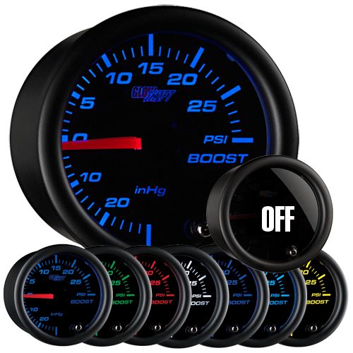

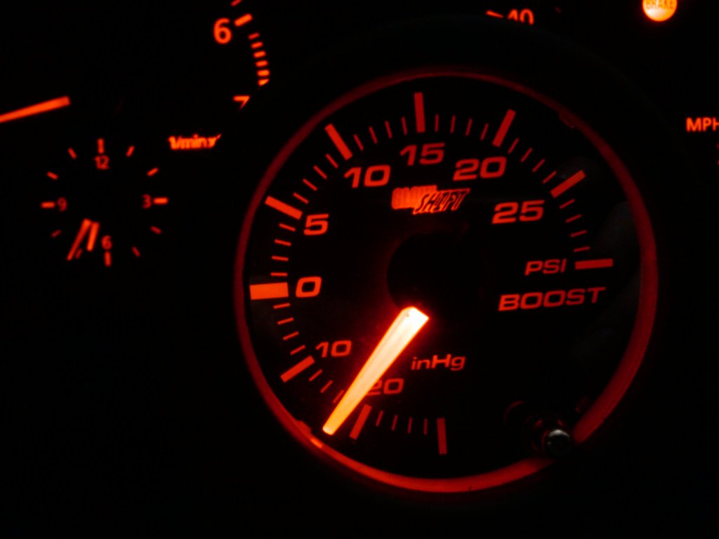
What this install will look like when it is all done:
Step 1: Take off the Fuse Cover. Slip a screwdriver under the bottom slit and gently work your way around clicking the two pinch clips out and removing the cover.
Step 2: Taking off the Knee Bolster
You need to take off 4 bolts holding it onto the dash. Pictured below:
Here is where the bolt is near the fuses:

The next two you are going to have to take these plastic covers off to get to. Take a small flat head screwdriver and gently pry it off. It doesn't really seem like you can scratch anything, so don't be too afraid.

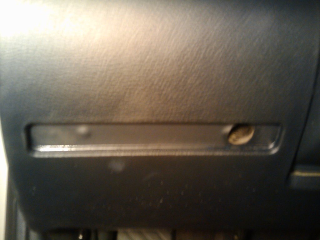
Just below this one there is another bolt you will be taking off. I didn't snap a pic of it, but you can't miss it. It's on the bottom right.

Make sure to unfasten your OBD port and lighting wiring from the knee bolster so you don't hurt the wires while doing this. Now remove the knee bolster out of the car and out of the way.

Now that is done it is time to go into the engine bay and do some work
Step 3: Run your vacuum tubing.
I decided to run it through where my ECU is. I have no clue if this is a good idea, but I didn't want to drill anything out.
Here is the picture of where I ran it. See the rubber nipple here? I cut that and ran the hose through there and into my knee bolster area:
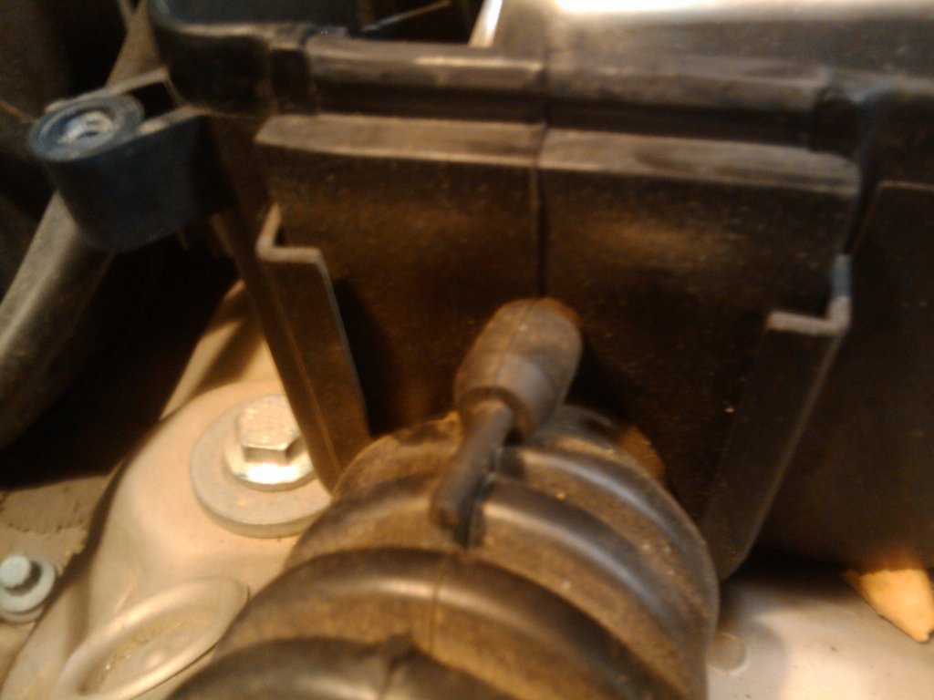
After it has been cut:
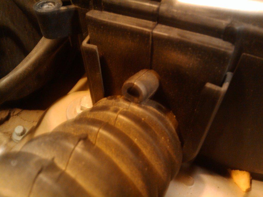
Now getting to all of the bolts to take off the ECU is a pain. You need to take off your windshield wiper blade assembly to get to it. Which is easy. All you need to do is take off the cap at the base of the assembly. Pop it off and remove the nut that is holding it in place. After removal of this nut wiggle the assembly a bit to scoot it off.
After this you will need to remove the rain guard. There are just a couple flat head plastic screws that are pictured below (above and to the right and left of the nut you just removed) and pull it away from the ECU housing.
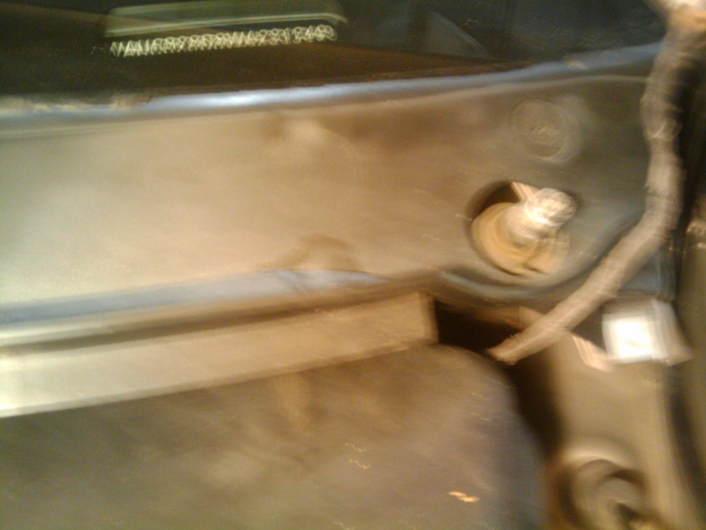
Remove the 5(i think) screws holding the housing down.
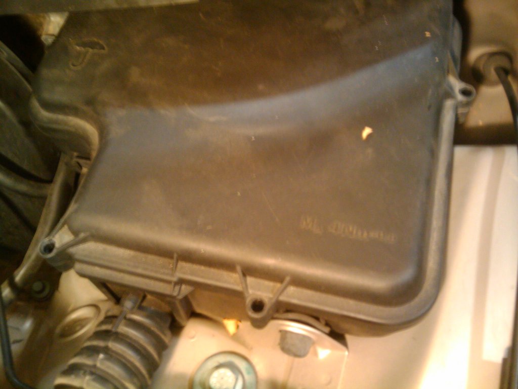
Now push the vacuum tubing through the grommet: This is where i found out my car is already chipped :P
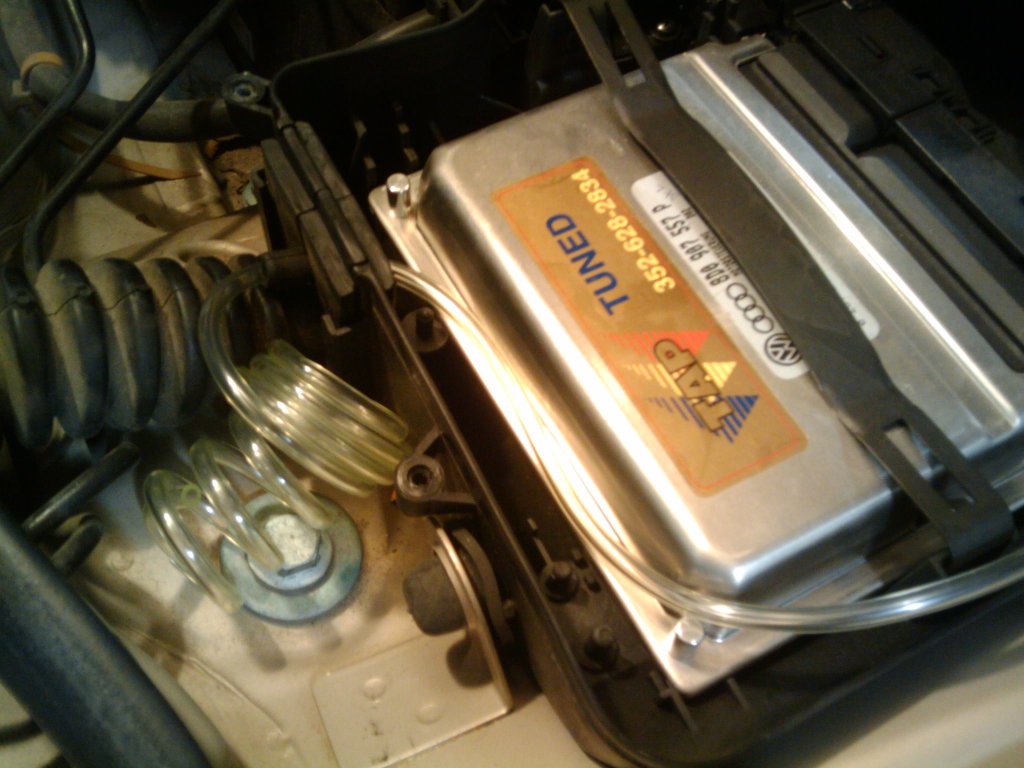
Everything else from this point will not have pictures so I will try to explain it to the best of my ability or find pictures to help.
Push the tubing through enough so you can see it come out where your knee bolster is. Now onto hooking it up to your engine.
Find a grommet on your fire wall to run your vacuum tubing through to your engine bay. I found one that had an open slot right behind the middle of my engine.
Now slip the vacuum tubing into the 1/4" rubber hose you bought. You only need to slip it in about 6" or so and then zip tie the end of the rubber hose where it meets the vacuum tubing.
Now run the rubber hosing to the first bank of your intake manifold. Cut to length.
There will be a small braided hose coming from the very front of your intake manifold. You are going to be cutting this to run your tee that comes with your GlowShift Boost Gauge to splice it so you can get a reading to your gauge. Cut this braided hose and insert the straight side of the tee to each side of this hose. Zip ties these ends.
Now you will be inserting the empty end of the tee into the rubber hose you have added to the vacuum tubing. Zip tie all ends.
Now you are done with the easy stuff. Push all remaining clear vacuum tubing into the inside of your car. Make sure everything is fastened tight and start re-assembling your engine bay. Put your rain guard, windshield wiper, and ECU housing back on.
Now everything on here will be wiring and connecting the gauge.
Step 5: Wiring.
Take your boost gauge and set it in front of you. You will be extending the wires on the back of the gauge so they can reach your fuse box location. You will need to extend them about 10 inches or so but do more just in case, because you can always shorten them if need be.
Cut (3) 12" sections of your 16 GA Primary Wire. (I didn't use the orange wire...the dimming wire. I don't see it being needed.) Take the 22-18 butt connectors and connect them to all the wires on the backside of the except the orange one. I just taped the orange wire off so there isn't any metal wire showing so it doesn't accidentally touch anything in your dash.
Now pull the vacuum tubing through your ECStuning.com Steering Wheel Column Pod and connect it to your gauge. Make sure you push it on as far as you can. Don't want that thing falling off.
Push all of the wires you extended through the Column Pod and set on top of your steering wheel. Push the gauge onto the column pod. The bod is beveled so it will be tight to get the gauge in. That's good because it will hold the gauge securely.
Pull all of your wire and the tubing through the top of your steering wheel. Place double sided tape on the front bottom of the pod. Place to sticks long ways on the left and right side bottom of the pod to secure it to your steering wheel. Press gently on the top of the pod to secure it to your steering wheel.
Run your wires to the empty space above your fuse box. Crimp your 22-18 #10 Spade (Fork) Nylon Terminal to the end of your black wire. Now attach your black wire (Ground) to the top bolt of your fuse panel and screw it behind it.
Attach your yellow and red wire to your 2 fuse taps.
Insert your 10 ATO Fuses into the rear part of the fuse taps on each of these.
Your yellow wire will go in place of a constant power. Which is something like your Radio fuse. How these fuse taps work is you take the fuse you are replacing it with and put it in the first slot of this fuse tap. Then you put a #10 ATO Fuse into the rear and insert the fuse tap in its' place.
Your red wire will go in place of a switched power. Which is something like your Power Windows fuse. Basically anything that turns on with your ignition.
Step 6: Test your finished product.
When you turn your car on the gauge should light up. Scroll trough the lights by pushing the silver button on the face of the gauge. I did the red because it matches really well to our stock color. Now turn your car off and back on. The gauge should remember what color you switched to.
Now you need to check if the tubing was installed correctly. Turn your car on and make sure the gauge is reading a vacuum pressure of around 20. Vacuum is below ZERO and boost is above ZERO.
If all is good go ahead and put everything back together.
DO NOT forget to make sure your fuse taps are not wiggling and are inserted well. Your fuse cover may not go back the way it did before so your are going to have to mess with the fuse taps to get the fuse cover back on. How i solved this was i flipped the fuse taps upside down and my fuse cover slipped back on perfectly.
I hope this write up was good. Please let me know if I made any mistakes so I can fix it. Thanks for reading and feel free to PM me if you have any questions about this DIY.
Thanks!
DISCLOSURE: I am not responsible for you cutting your finger, blowing a fuse, shortwiring your ECU, or your GF leaving you because you did this on your anniversary. This is just a write up on what I did to make this possible.
1998 Audi a4 1.8T AEB Engine Code
What you will be needing for this DIY:
Basic Tools Including
*Crimper/Wire Stripper
*8mm Socket
*Double Sided Tape
*2 each 10 ATO Fuses
*22-18 #10 Spade (Fork) Nylon Terminal
*3 each 22-18 Nylon Butt Connectors
*1/4 ID Hose (2 Feet or so)
*2 each of Auto Zone part # BP-HHA-RP Fuse Taps
*4 each hose clamps or zip ties
*Wire Cutters
*16 Gauge Primary Wire
*And a couple other Metric Sockets (Forgot what size to take off windshield wiper and ECU casing)
*ECStuning.com part # ES2413
*Ebay.com for the Glowshift 7 LED
What this install will look like when it is all done:
Step 1: Take off the Fuse Cover. Slip a screwdriver under the bottom slit and gently work your way around clicking the two pinch clips out and removing the cover.
Step 2: Taking off the Knee Bolster
You need to take off 4 bolts holding it onto the dash. Pictured below:
Here is where the bolt is near the fuses:
The next two you are going to have to take these plastic covers off to get to. Take a small flat head screwdriver and gently pry it off. It doesn't really seem like you can scratch anything, so don't be too afraid.
Just below this one there is another bolt you will be taking off. I didn't snap a pic of it, but you can't miss it. It's on the bottom right.
Make sure to unfasten your OBD port and lighting wiring from the knee bolster so you don't hurt the wires while doing this. Now remove the knee bolster out of the car and out of the way.
Now that is done it is time to go into the engine bay and do some work
Step 3: Run your vacuum tubing.
I decided to run it through where my ECU is. I have no clue if this is a good idea, but I didn't want to drill anything out.
Here is the picture of where I ran it. See the rubber nipple here? I cut that and ran the hose through there and into my knee bolster area:
After it has been cut:
Now getting to all of the bolts to take off the ECU is a pain. You need to take off your windshield wiper blade assembly to get to it. Which is easy. All you need to do is take off the cap at the base of the assembly. Pop it off and remove the nut that is holding it in place. After removal of this nut wiggle the assembly a bit to scoot it off.
After this you will need to remove the rain guard. There are just a couple flat head plastic screws that are pictured below (above and to the right and left of the nut you just removed) and pull it away from the ECU housing.
Remove the 5(i think) screws holding the housing down.
Now push the vacuum tubing through the grommet: This is where i found out my car is already chipped :P
Everything else from this point will not have pictures so I will try to explain it to the best of my ability or find pictures to help.
Push the tubing through enough so you can see it come out where your knee bolster is. Now onto hooking it up to your engine.
Find a grommet on your fire wall to run your vacuum tubing through to your engine bay. I found one that had an open slot right behind the middle of my engine.
Now slip the vacuum tubing into the 1/4" rubber hose you bought. You only need to slip it in about 6" or so and then zip tie the end of the rubber hose where it meets the vacuum tubing.
Now run the rubber hosing to the first bank of your intake manifold. Cut to length.
There will be a small braided hose coming from the very front of your intake manifold. You are going to be cutting this to run your tee that comes with your GlowShift Boost Gauge to splice it so you can get a reading to your gauge. Cut this braided hose and insert the straight side of the tee to each side of this hose. Zip ties these ends.
Now you will be inserting the empty end of the tee into the rubber hose you have added to the vacuum tubing. Zip tie all ends.
Now you are done with the easy stuff. Push all remaining clear vacuum tubing into the inside of your car. Make sure everything is fastened tight and start re-assembling your engine bay. Put your rain guard, windshield wiper, and ECU housing back on.
Now everything on here will be wiring and connecting the gauge.
Step 5: Wiring.
Take your boost gauge and set it in front of you. You will be extending the wires on the back of the gauge so they can reach your fuse box location. You will need to extend them about 10 inches or so but do more just in case, because you can always shorten them if need be.
Cut (3) 12" sections of your 16 GA Primary Wire. (I didn't use the orange wire...the dimming wire. I don't see it being needed.) Take the 22-18 butt connectors and connect them to all the wires on the backside of the except the orange one. I just taped the orange wire off so there isn't any metal wire showing so it doesn't accidentally touch anything in your dash.
Now pull the vacuum tubing through your ECStuning.com Steering Wheel Column Pod and connect it to your gauge. Make sure you push it on as far as you can. Don't want that thing falling off.
Push all of the wires you extended through the Column Pod and set on top of your steering wheel. Push the gauge onto the column pod. The bod is beveled so it will be tight to get the gauge in. That's good because it will hold the gauge securely.
Pull all of your wire and the tubing through the top of your steering wheel. Place double sided tape on the front bottom of the pod. Place to sticks long ways on the left and right side bottom of the pod to secure it to your steering wheel. Press gently on the top of the pod to secure it to your steering wheel.
Run your wires to the empty space above your fuse box. Crimp your 22-18 #10 Spade (Fork) Nylon Terminal to the end of your black wire. Now attach your black wire (Ground) to the top bolt of your fuse panel and screw it behind it.
Attach your yellow and red wire to your 2 fuse taps.
Insert your 10 ATO Fuses into the rear part of the fuse taps on each of these.
Your yellow wire will go in place of a constant power. Which is something like your Radio fuse. How these fuse taps work is you take the fuse you are replacing it with and put it in the first slot of this fuse tap. Then you put a #10 ATO Fuse into the rear and insert the fuse tap in its' place.
Your red wire will go in place of a switched power. Which is something like your Power Windows fuse. Basically anything that turns on with your ignition.
Step 6: Test your finished product.
When you turn your car on the gauge should light up. Scroll trough the lights by pushing the silver button on the face of the gauge. I did the red because it matches really well to our stock color. Now turn your car off and back on. The gauge should remember what color you switched to.
Now you need to check if the tubing was installed correctly. Turn your car on and make sure the gauge is reading a vacuum pressure of around 20. Vacuum is below ZERO and boost is above ZERO.
If all is good go ahead and put everything back together.
DO NOT forget to make sure your fuse taps are not wiggling and are inserted well. Your fuse cover may not go back the way it did before so your are going to have to mess with the fuse taps to get the fuse cover back on. How i solved this was i flipped the fuse taps upside down and my fuse cover slipped back on perfectly.
I hope this write up was good. Please let me know if I made any mistakes so I can fix it. Thanks for reading and feel free to PM me if you have any questions about this DIY.
Thanks!
Last edited by xxNeverG1veUpxx; Oct 26, 2012 at 10:32 AM.

Nice write up man! I lol'd at the disclaimer. Only comment I have is that going through the ECU box seems like a lot of extra work. I poked a hole through an un-used rubber grommet just inboard of the ECU box, which puts the vac line in perfect position to be T'd into the vac line from the manifold to the FPR.
Overall though, great write up! Vote to move to DIY area with linky in FAQ's
Only comment I have is that going through the ECU box seems like a lot of extra work. I poked a hole through an un-used rubber grommet just inboard of the ECU box, which puts the vac line in perfect position to be T'd into the vac line from the manifold to the FPR.Overall though, great write up! Vote to move to DIY area with linky in FAQ's
Thanks CCA4. Pretty new to the Modifying scene, but I'm learning. The only reason I went through the ECU area is because I immediately saw it, so I didn't have to go searching anywhere else.
Your idea would probably have worked better though. Thanks for reading!
Your idea would probably have worked better though. Thanks for reading!


1st Gear
Joined: Aug 2012
Posts: 74
From: South East Connecticut
i used ecu box for amp power wire.
one other suggestion tho, run the power wire from something that wont kill the car. like power windows horn etc. if somehow you mess the fuel pump fuse up, car can die. thats just the way i do it, but your way is fine.
one other suggestion tho, run the power wire from something that wont kill the car. like power windows horn etc. if somehow you mess the fuel pump fuse up, car can die. thats just the way i do it, but your way is fine.
Thanks!

Thread
Thread Starter
Forum
Replies
Last Post
